

 English
 简体中文

A 400 A feeder with 500 kcmil copper phase conductors is ready for inspection. The installer used a 6 AWG equipment grounding conductor. The inspector checks the overcurrent device rating and asks for the calculation. The correct minimum copper size from NEC Table 250.122 is 3 AWG, and because the phase conductors were upsized for voltage drop, the grounding conductor may need to be larger still. This is where a ground wire size calculator earns its place: it should apply the governing rule, show the base size, and flag the adjustments.
The short answer: size the equipment grounding conductor from the overcurrent protective device rating first, then adjust for conductor material, parallel runs, and any upsizing of the phase conductors. A calculator is useful only when it exposes those steps rather than hiding them behind a single number.
What a Ground Wire Size Calculator Should Actually Do
A reliable calculator is a decision aid, not an oracle. For a typical low-voltage feeder, it should ask for the overcurrent device rating, the grounding conductor material, the code edition, and whether the circuit uses parallel raceways. It should then return a minimum size and a short list of checks.
That output matters because grounding conductor sizing is not the same as phase conductor sizing. Phase conductors are selected for ampacity and voltage drop; the equipment grounding conductor is selected to carry fault current safely until the overcurrent device clears the fault. A calculator that only asks for load current is answering the wrong question.
Useful inputs include:
- Overcurrent device rating and trip curve, not just the load current.
- Copper or aluminum grounding conductor, because the minimum sizes differ.
- Code edition and installation type, such as feeder, branch circuit, service, or separately derived system.
- Whether phase conductors are paralleled in multiple raceways.
- Whether phase conductors were upsized above the minimum ampacity size.
The Core Rule: Start With the Overcurrent Device
Under NEC 250.122, the equipment grounding conductor for a feeder or branch circuit is generally sized from the rating of the overcurrent device ahead of the circuit. Common copper sizes are 14 AWG at 15 A, 12 AWG at 20 A, 8 AWG at 100 A, 6 AWG at 200 A, and 3 AWG at 400 A. The table is the baseline.
| Overcurrent device rating | Copper EGC | Aluminum EGC |
|---|---|---|
| 20 A | 12 AWG | 10 AWG |
| 60 A | 10 AWG | 8 AWG |
| 100 A | 8 AWG | 6 AWG |
| 200 A | 6 AWG | 4 AWG |
| 400 A | 3 AWG | 1 AWG |
| 600 A | 1 AWG | 2/0 AWG |
| 1000 A | 2/0 AWG | 4/0 AWG |
Other standards use a different logic. IEC 60364 and BS 7671 often begin with the cross-sectional area of the line conductor and apply a ratio or an adiabatic check. That is why a calculator must state which code it follows. A number without a code reference is not a design result; it is a guess with a decimal point.
From Breaker Rating to Conductor Size: A Worked Example
Take a 400 A, three-phase feeder with copper phase conductors and 75°C terminations. The base copper EGC from Table 250.122 is 3 AWG. If the same circuit used aluminum, the base size would be 1 AWG. If the phase conductors were increased from 500 kcmil to 600 kcmil for voltage drop, NEC 250.122(B) may require the EGC to be increased proportionally. The calculator should flag that condition, not silently return 3 AWG.
The chart below shows why the result is not linear. A 100 A circuit may use 8 AWG copper, while a 1000 A circuit may use 2/0 AWG copper. The jump reflects fault current and clearing performance, not a simple ratio of amperes to wire gauge.
The bar heights are illustrative. The practical point is that grounding conductor size is tied to the protective device and fault path, so a calculator should show the code basis and adjustment flags beside the result.
Where Calculators Go Wrong: Material, Temperature, and Installation
Material is the first common error. Aluminum grounding conductors are permitted in many installations, but they require larger sizes than copper for the same overcurrent rating. They also need aluminum-listed connectors and corrosion protection. A calculator that returns a copper size and leaves the material field blank is not finished.
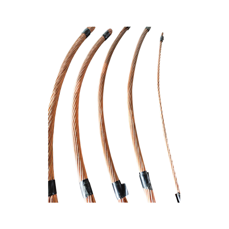
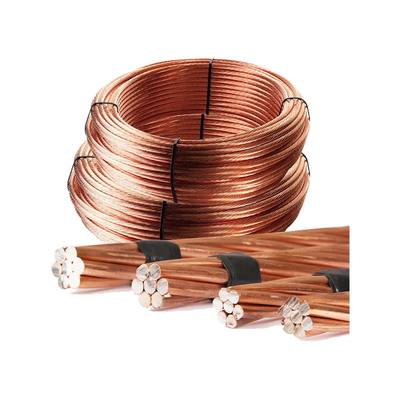
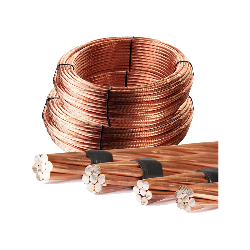 Copper-Clad Steel Stranded Wire for EarthingCopper-clad steel stranded earthing wire combines a steel core with copper for flexible, durable grounding runs where copper cost and strength matter.View Product →
Temperature and short-circuit withstand are the second gap. The table gives a minimum size for fault clearing, but it does not prove the conductor can survive a high available fault current for the clearing time. An adiabatic check using the conductor material, temperature limits, and protective device clearing time may call for a larger conductor. This is especially relevant near large transformers and in industrial systems with high fault energy.
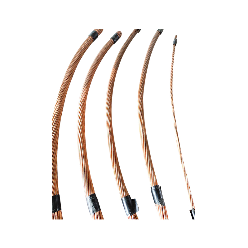 High-Purity Copper Stranded Earthing WireHigh-purity copper stranded earthing conductor offers flexible routing, corrosion resistance, and low grounding resistance; available in hard-drawn, soft-drawn, or tinned copper.View Product →
Installation method is the third gap. Parallel phase conductors in separate raceways generally require a full-size equipment grounding conductor in each raceway under NEC 250.122(F). A calculator that treats a parallel feeder as one large circuit can understate the total copper required. Direct burial, cable tray, and raceway installations also affect connector selection and corrosion protection.
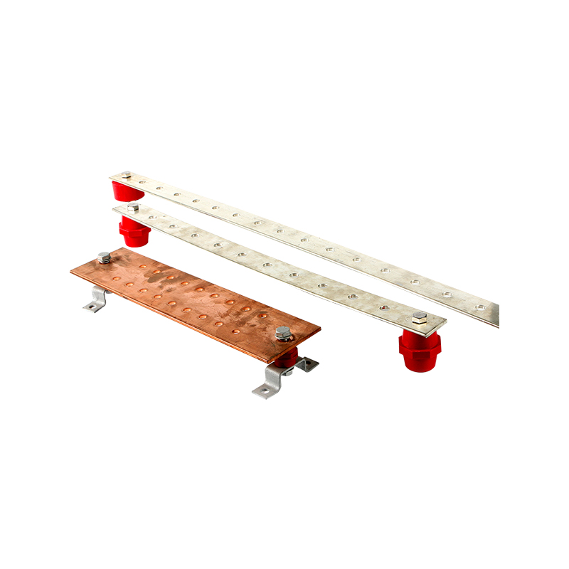 Customizable Grounding Bus Bar for Power EquipmentGrounding bus bar provides a low-resistance, easy-to-install connection for high- and low-voltage equipment; size, material, and bracket can be customized.View Product →
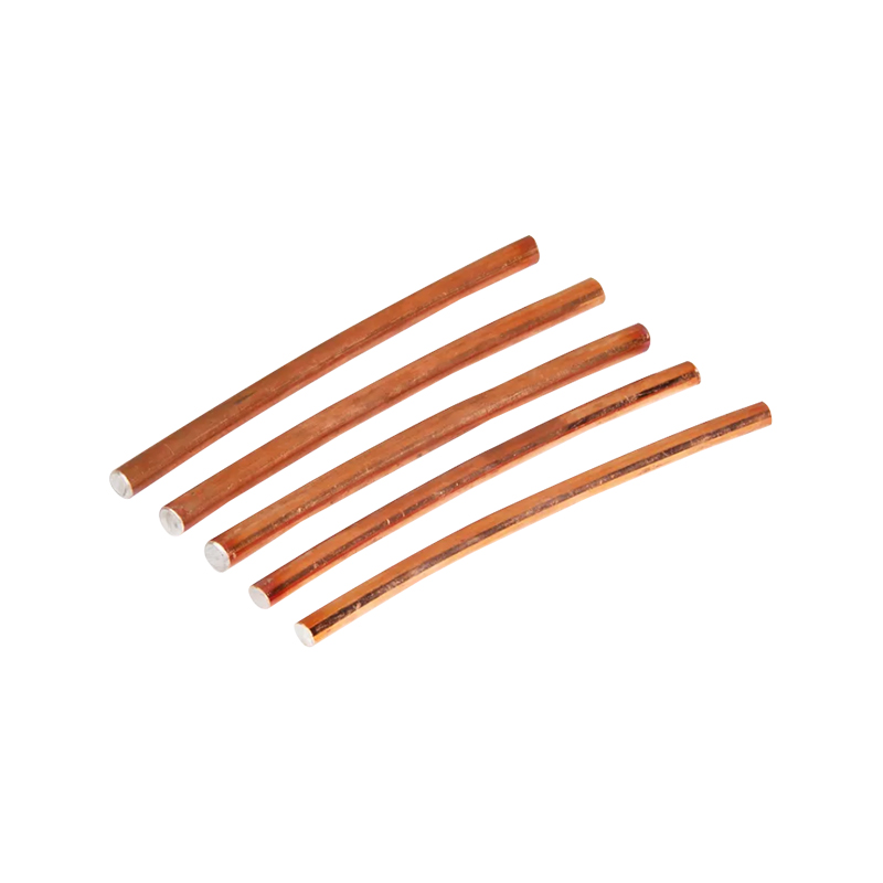
When the calculated size falls between standard products, choose the next larger available conductor. For copper-clad steel stranded wire, copper stranded wire, and copper bar, confirm cross-sectional area, material, and termination compatibility.
A Practical Sizing Workflow
Use the calculator as a structured check, not a black box. A practical workflow looks like this:
- Identify the circuit, overcurrent device, and governing code edition; record the device rating and clearing time if available.
- Find the base grounding conductor size from the code table using the overcurrent device rating and conductor material.
- Check whether the phase conductors were upsized above the minimum ampacity size. If so, apply the proportional increase rule.
- Check parallel raceways. If the circuit is paralleled, confirm whether each raceway needs a full-size grounding conductor.
- Run a short-circuit withstand check for high-fault-current locations. Increase the size if the table size cannot withstand the fault energy.
- Match the conductor to listed connectors, clamps, and terminations. Confirm material compatibility and corrosion protection.
- Document the inputs, code references, result, and adjustments on the design drawing or inspection record.
For the conductor and connection side of the design, review the available grounding conductors and the matching grounding rod connectors before releasing the bill of materials.
Reading the Result: What the Output Should Tell You
A good calculator output has three parts: the minimum code size, the governing rule, and the adjustment flags. If the result says "3 AWG copper" without stating the 400 A device, the NEC table, the parallel-run status, and the upsizing check, the designer still has work to do. The same number can be correct in one installation and wrong in another.
Pay attention to the difference between a minimum size and a selected size. The minimum size is the code floor. The selected size may be larger because of short-circuit withstand, voltage drop coordination, future load, or stock availability. That is normal. What is not normal is selecting a smaller conductor because it fits a connector or because the calculator defaulted to the wrong material.
Also check the units and the wire gauge system. AWG sizes get smaller as the number gets larger, while kcmil sizes get larger as the number gets larger. A calculator that mixes 3 AWG and 3 kcmil is not a rounding issue; it is a safety issue. Confirm the result in the same units used on the drawing and the purchase order.
Final Takeaway
Use a ground wire size calculator to organize the code check, not to replace it. Start with the overcurrent device rating, confirm the conductor material, apply the upsizing and parallel-run rules, and check short-circuit withstand where fault energy is high. Then verify that the selected conductor, connector, and termination are compatible and documented. That process turns a simple calculator result into a grounding design that can be inspected, installed, and maintained without surprises.

 About Us
 +86-15167536268

 29, Xingmei Avenue, Xinchang, Zhejiang, China
