

 English
 简体中文

A 4/0 AWG copper conductor appears three times in a standard copper ampacity chart: 195 A at 60 °C, 230 A at 75 °C and 260 A at 90 °C. Every figure is correct, and none of them is automatically the number a project needs. The value that belongs in a cable schedule is the lowest of three limits, namely the conductor's derated ampacity, the temperature rating of the termination it lands on, and the effect of ambient temperature and grouping.
That is the short answer, and it is worth stating before any table: read the chart backwards from the weakest component in the circuit, apply the corrections, and size from the result. Sizing straight from the 90 °C column is how a design ends up 20–30% optimistic before anyone checks the rating stamped on the lug.
What a Copper Ampacity Chart Actually Measures
Ampacity is the maximum continuous current a conductor can carry while its insulation stays within its rated temperature and ages at a predictable rate. It is a thermal limit rather than an electrical one. A copper conductor has the same resistance at 10 A and at 200 A, but the heat it generates rises with the square of the current, while the heat it sheds depends on surface area, installation method and surrounding temperature.
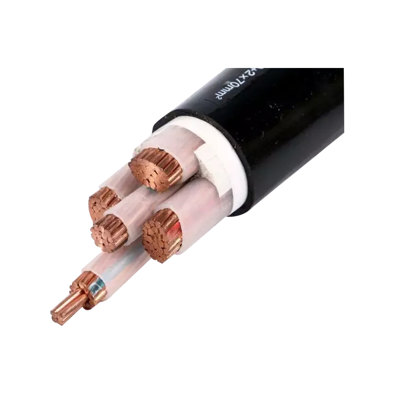
Six inputs move the number on the page: cross-section in AWG, kcmil or mm²; conductor material and conductivity grade; insulation and jacket temperature rating; installation method such as free air, raceway, tray or buried duct; ambient temperature; and the number of current-carrying conductors sharing the same enclosure. Change any one of them and the same copper can be listed twenty or thirty amperes apart.
| Size (AWG/kcmil) | Area (mm², approx.) | 60 °C | 75 °C | 90 °C |
|---|---|---|---|---|
| 10 | 5.3 | 30 A | 35 A | 40 A |
| 8 | 8.4 | 40 A | 50 A | 55 A |
| 6 | 13.3 | 55 A | 65 A | 75 A |
| 4 | 21.2 | 70 A | 85 A | 95 A |
| 2 | 33.6 | 95 A | 115 A | 130 A |
| 1/0 | 53.5 | 125 A | 150 A | 170 A |
| 2/0 | 67.4 | 145 A | 175 A | 195 A |
| 4/0 | 107 | 195 A | 230 A | 260 A |
| 250 kcmil | 127 | 215 A | 255 A | 290 A |
| 500 kcmil | 253 | 320 A | 380 A | 430 A |
Two conventions need checking before any number is quoted. AWG and kcmil tables usually assume 30 °C ambient air and a defined conduit fill, while IEC tables may assume 30 °C in air but 20 °C in the ground, with different grouping factors. A 25 mm² value lifted from an IEC table will not line up neatly against an AWG list, because 25 mm² sits between 4 AWG at roughly 21.2 mm² and 3 AWG at roughly 26.7 mm². Mixing the two systems in one schedule is a common source of confusion at the tender stage.
Why the Same Copper Shows Three Different Ampacities
The three columns exist because insulation fails on a temperature curve. PVC compounds are typically rated 70 °C or 75 °C, XLPE and EPR reach 90 °C, and the 60 °C column survives mainly for legacy rubber insulation and for equipment marked for 60 °C terminations. A 90 °C conductor is not "better copper"; it is the same copper with insulation that tolerates more heat before it embrittles or deforms.
The second limit sits at the ends of the cable. Terminal blocks, lugs and breaker pads are rated separately, and the common rule is that circuits above 100 A are assumed to use 75 °C terminations unless the equipment is marked otherwise. A 90 °C XLPE cable landed on a 75 °C lug is therefore capped at the 75 °C value, and the extra thermal headroom only becomes useful when it is consumed by derating.
That is the practical conclusion for specification work: choose the 90 °C product for the headroom it gives you in hot plant rooms and crowded trays, but never present the 90 °C column as the circuit rating without confirming the termination. Where the two disagree, the lower number governs, and the difference often explains why two suppliers quote the same cable with suspiciously different current claims.
Copper Ampacity by Size: Where the Curve Bends
Ampacity does not scale with cross-section. Moving from 6 AWG to 500 kcmil multiplies conductor area by roughly nineteen, but ampacity at 90 °C rises only from 75 A to 430 A, a factor of about 5.7. Heat leaves the conductor through its surface, and surface grows with diameter rather than area, so each additional square millimetre of copper buys a little less current than the one before it.
Copper ampacity at 75 °C (dark) and 90 °C (light), amperes, same installation basis as the table above.
6 AWG
65 / 75 A
2 AWG
115 / 130 A
1/0 AWG
150 / 170 A
4/0 AWG
230 / 260 A
500 kcmil
380 / 430 A
Bars are scaled to 430 A. The visual gap between the two ratings narrows in absolute terms as size grows, which is why derating penalties hurt small conductors proportionally more than large ones.
This bend has two practical consequences. First, several smaller parallel conductors can dissipate heat better than one large conductor of the same total area, but each parallel run then attracts grouping factors and every run needs its own termination space. Second, voltage drop behaves in the opposite direction to heat, so long runs are usually driven by drop rather than by the current column, and a conductor that passes the ampacity check can still fail the drop check by a wide margin.
Derating: The Corrections That Change the Final Number
Correction factors are where chart values turn into design values. The sequence below is the one worth following, using a 1/0 AWG XLPE copper conductor as the worked case.
- Start from the table value at the insulation rating: 170 A at 90 °C.
- Apply the ambient correction. At 45 °C air the factor for a 90 °C conductor is about 0.87, giving roughly 148 A.
- Apply the grouping factor for the number of loaded conductors sharing the raceway. Six conductors typically use 0.80, giving roughly 118 A.
- Compare with the termination limit of 150 A at 75 °C. The termination is not the binding constraint here.
- Apply the continuous-load rule, which requires the conductor to be rated at least 125% of the continuous load. The usable continuous load falls to about 94 A.
Run the same conductor on 60 °C lugs and the picture changes again: the cap drops to 125 A, and after the same corrections the circuit is limited to roughly 87 A. A designer who read only the 90 °C column would have overstated capacity by almost 100% before corrections were applied, and by about 35% after them. That gap is the real cost of an unchecked chart reference, and it is far cheaper to catch on paper than during commissioning.
Ampacity Is Not the Whole Story for Earthing Conductors
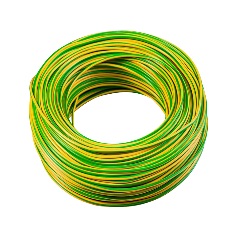
Earthing conductors are sized differently. The equipment grounding conductor is generally selected from a table keyed to the rating of the upstream overcurrent device rather than to load current: a 200 A device calls for 6 AWG copper, 400 A for 3 AWG, 600 A for 1 AWG, and the ladder continues upward with device rating. The ampacity chart tells you very little about that selection.
What governs instead is short-time withstand. The adiabatic check is S = √(I²t) / k, where S is the conductor area in mm², I the fault current in amperes, t the clearing time in seconds and k a material and insulation constant: about 143 for copper with PVC insulation and 176 for copper with XLPE, taken from IEC 60364-5-54. A 35 mm² copper PVC earthing conductor therefore absorbs roughly 5 kA for one second. Longer clearing times or higher fault levels push the area up quickly, which is why protection settings and conductor size are always reviewed together.
The same logic explains why earthing hardware is specified by joint resistance and short-circuit withstand rather than by continuous ampacity, and why the underlying withstand question deserves its own review. The mechanics behind that check are set out in this note on how much current earthing conductors withstand during a fault, which pairs well with the chart values above.
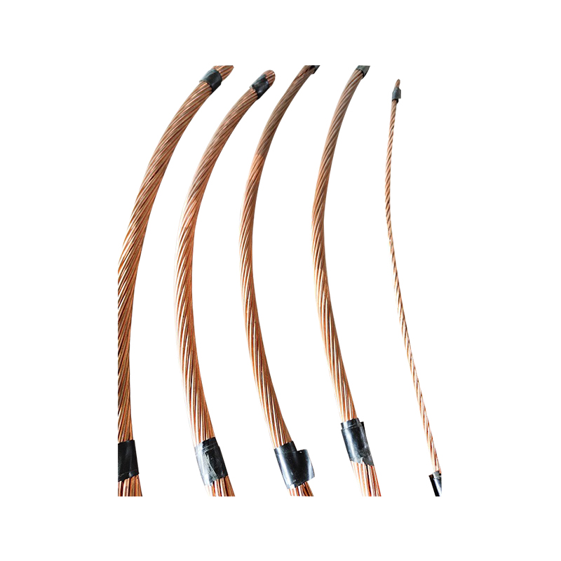
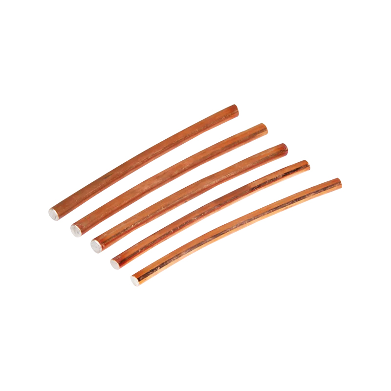
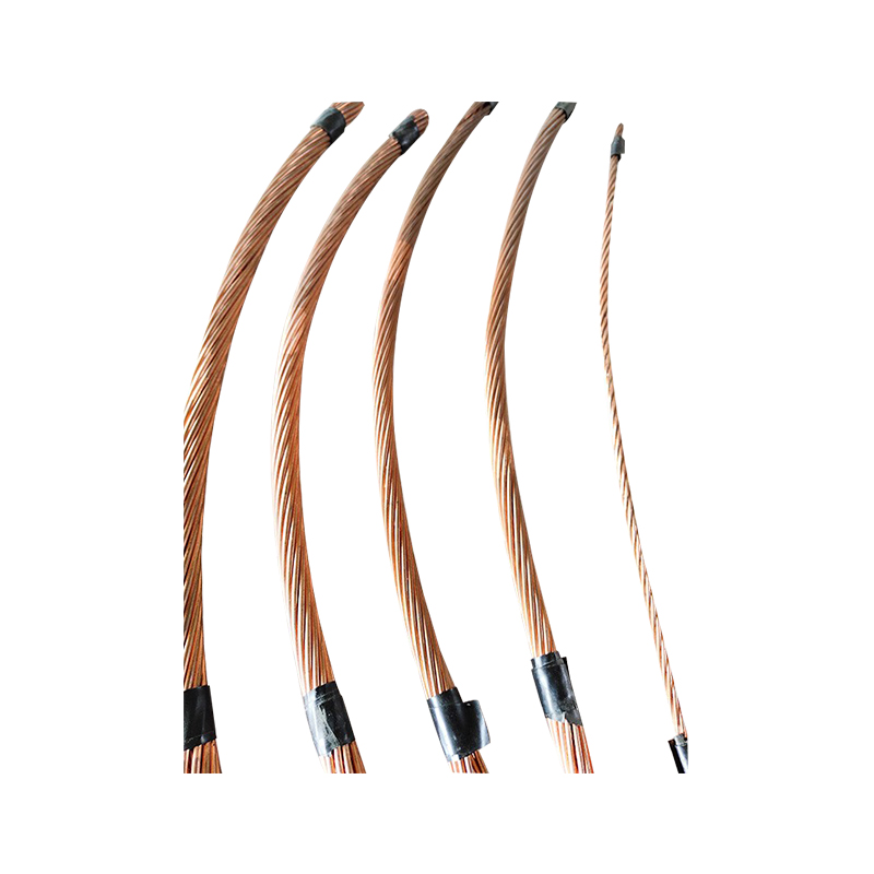 Earthing Copper Stranded Wire for GroundingHigh-purity stranded copper earthing conductor available in hard-drawn, soft-drawn or tinned forms, suited to power equipment grounding where fault-current withstand is being reviewed.View Product →
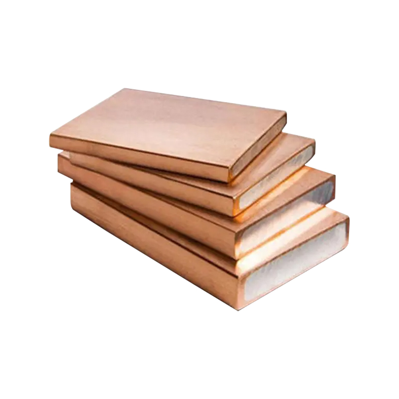
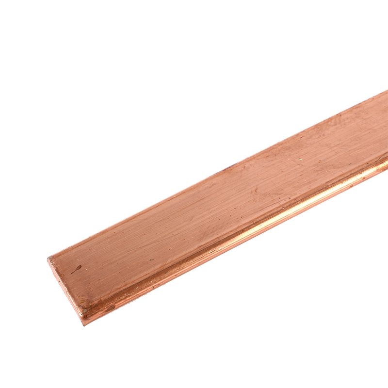 Oxygen-Free Copper Earthing Bar for GroundingOne-grade oxygen-free copper bar with up to 99.97% copper and low resistivity, relevant when comparing bare busbar ratings and temperature-rise bases for grounding projects.View Product →
Bare copper bar and stranded copper conductors behave differently from insulated cable in these calculations. A busbar has no jacket limiting its temperature, but published bar ratings vary by 30–50% between sources because orientation, spacing, plenum conditions and permitted temperature rise all differ. When comparing a 25 × 3 mm bar quoted at 250 A against one quoted at 350 A, check the temperature-rise basis before assuming either is wrong.
What to Put on the Purchase Order
Because so much of the chart depends on context, the ordering document should carry the numbers that fix it. Specify the conductor standard (IEC 60228 class 2 for stranded copper, or ASTM B8 where imperial sizing applies), the nominal cross-section, and the maximum DC resistance at 20 °C: 25 mm² copper should not exceed about 0.727 Ω/km and 95 mm² about 0.193 Ω/km. State the insulation type and temperature rating, the stranding class, and the standard the test certificate will follow.
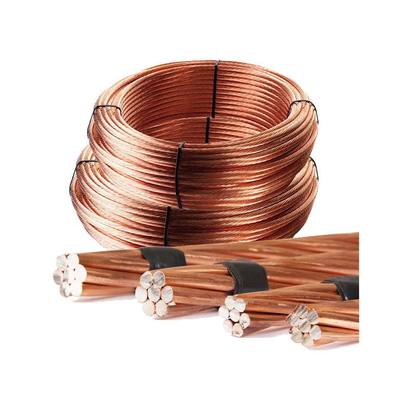
Where copper-clad steel or copper-clad aluminium is proposed as a substitute, the grade matters more than the diameter. Copper-clad steel is normally offered at 21%, 30% or 40% IACS conductivity, so a 40% grade carries roughly 40% of the current of the same-size solid copper conductor. A supplier who quotes only "copper-clad" without the conductivity grade has not answered the question.
Tolerances are the quiet commercial risk. A conductor supplied 2% under nominal diameter loses about 4% of its cross-section, which shows up as a few percent of extra resistance and a few degrees of extra running temperature over years of service. Calipers on a stranded conductor are unreliable; weighing a measured length, or measuring resistance on a bridge, settles the argument in minutes.
 Copper Braided Flexible Earthing ConnectorFlexible copper braid or foil grounding connector with pressed oxygen-free copper lug, silver- or tin-plated, for low-resistance paths where lug and joint performance matter.View Product →
Flexible connectors, braids and jumpers deserve the same discipline, since their ampacity is limited by the joint and the lug rather than by the conductor itself. Buyers working through a bill of materials often tie these items back to the earthing conductor range so that one specification covers the whole grounding path; the copper grounding wire range is a useful reference point when consolidating those line items.
Checks Worth Doing Before You Commit
- Confirm the temperature rating of every termination in the circuit, not just of the cable.
- Record the ambient design temperature and the number of loaded conductors per raceway; both are needed to justify the derated figure.
- Check whether the chart you are reading is built on AWG or metric assumptions, and never interpolate between the two systems.
- Verify fault level and clearing time for earthing and bonding conductors, since ampacity alone does not size them.
- Ask for resistance data and conductivity grade on any copper-clad alternative.
A copper ampacity chart is a starting point, not an answer. The number that survives review is the one that has been trimmed by ambient, grouping and termination limits, and then checked against fault withstand where the conductor is there to protect people rather than to carry load.
 About Us
 +86-15167536268

 29, Xingmei Avenue, Xinchang, Zhejiang, China
