

 English
 简体中文
简体中文
Service Grounding · NEC Reference
The rod count on the print rarely matches what actually gets installed in the ground.
Short answer: a 200 amp service needs at least one grounding rod, but code requires a second rod, spaced a minimum of six feet from the first, whenever a single rod tests above 25 ohms of resistance to earth. In practice, most residential and commercial 200A installations end up with two rods, because a lone rod rarely tests low enough on its own to satisfy that threshold.
Grounding rod count is one of the more commonly misunderstood parts of a 200 amp service installation. Some electricians drive one rod and move on; others drive two as a matter of habit. Neither approach is wrong on its own, but only one of them reliably satisfies the code requirement — and the difference comes down to a resistance test most contractors skip. The sections below walk through what actually determines rod count, how rods compare with other grounding electrode options, and what tends to fail inspection.
25 ohms
Maximum resistance-to-earth a single ground rod must test at to be code-compliant on its own.
6 ft min
Minimum required spacing between two ground rods when a second rod is installed.
8 ft deep
Standard driven depth for a single ground rod, unless rock or obstruction requires an alternate method.
The core ruleOne Rod vs Two Rods: What Actually Determines the Number Required
The National Electrical Code doesn't set a fixed rod count for a given service size — it sets a performance target instead. Under NEC 250.53(A)(2), a single rod electrode is acceptable only if it tests at 25 ohms of resistance to earth or less. If it doesn't, a second rod must be added, spaced at least six feet from the first. That single distinction is why "how many rods for 200A service" doesn't have a universal number — it has a universal test.
Code MinimumSingle Rod System
- Legal only if measured resistance is 25 ohms or less
- Most likely to pass in moist clay or loam soil
- Rarely passes in sandy, rocky, or dry soil conditions
- Requires a documented resistance test to prove compliance
Common PracticeTwo Rod System
- Automatically satisfies 250.53(A)(2) without a resistance test
- Standard default on most 200A residential and light commercial jobs
- Rods spaced a minimum of 6 feet apart, driven to matching depth
- More resilient across seasonal soil moisture changes
Because testing resistance in the field takes extra equipment and time, many contractors simply install two rods by default rather than gamble on a single rod passing. It's not a code requirement to skip testing — it's a practical shortcut that avoids a callback if the first rod fails.
Why testing mattersWhy a Single Ground Rod Almost Never Passes on Its Own
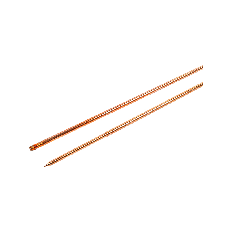
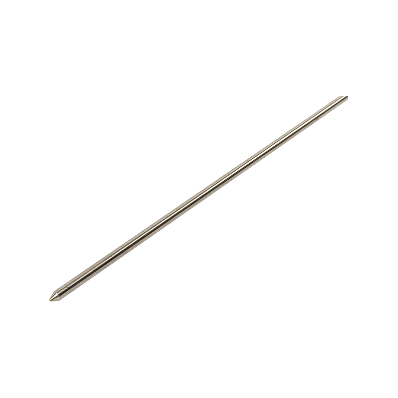
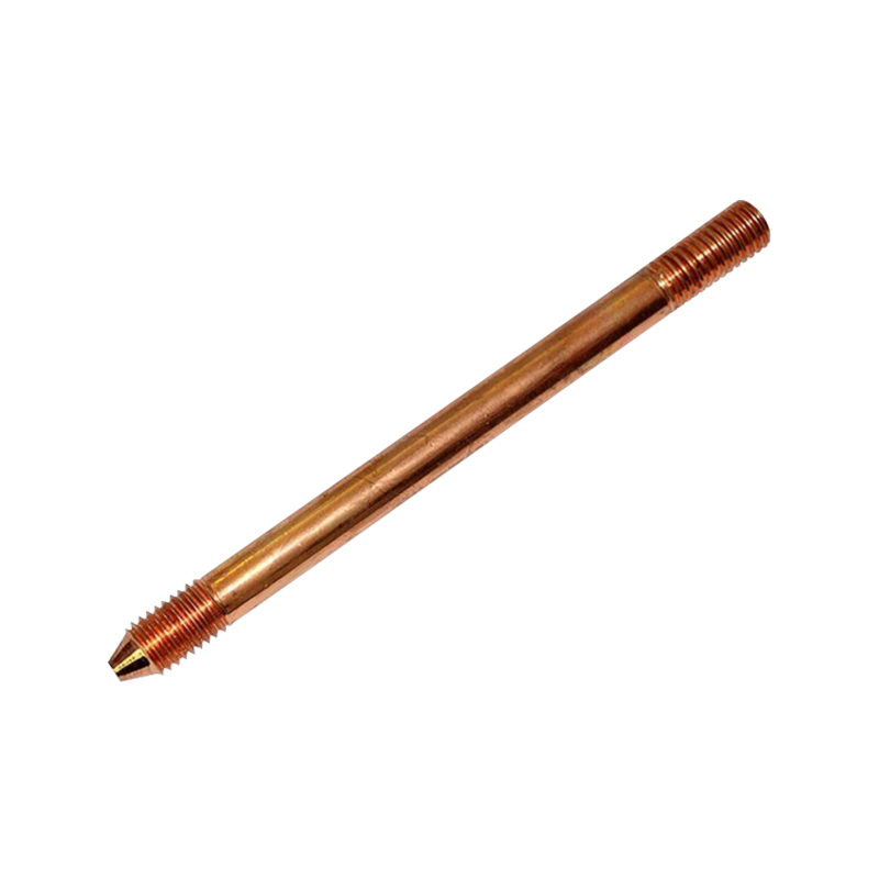
Soil composition drives resistance far more than rod quality or installation technique. A single 8-foot copper-clad rod can test anywhere from under 10 ohms to well over 100 ohms depending entirely on what it's driven into.
| Soil Type | Typical Resistance (single rod) | Likely Outcome |
| Wet clay or loam | 5–20 ohms | Often passes on one rod |
| Average garden soil | 20–50 ohms | Borderline; frequently needs a second rod |
| Sandy soil | 50–150 ohms | Almost always needs a second rod |
| Rocky or gravel soil | 100+ ohms | May need supplemental electrodes beyond rods |
This is also why regional experience matters more than a fixed rule of thumb. A contractor working primarily in a river-bottom clay area may rarely need a second rod, while one working in a sandy coastal region should plan for two rods on nearly every job.
Conductor sizingSizing the Grounding Electrode Conductor for a 200A Service
Rod count isn't the only sizing question tied to a 200A disconnect. The wire connecting the electrode system back to the service equipment has its own code-mandated size, based on NEC Table 250.66 and the service conductor size feeding the disconnect.
| Service Conductor | Standard GEC Size | Rod/Pipe/Plate Exception |
| 2/0 copper (typical 200A) | 4 AWG copper | 6 AWG copper allowed for rod, pipe, or plate electrodes |
| 4/0 aluminum (typical 200A) | 2 AWG aluminum | 4 AWG copper allowed for concrete-encased electrodes |
That exception matters in the field: a conductor sized for a rod-only system can sometimes be one size smaller than what's required for other electrode types, which is worth double-checking before assuming a single conductor spec applies across the whole grounding system.
Beyond rodsGround Rods Compared to Other Grounding Electrodes
Rods are the most common grounding electrode, but they're not the only option NEC 250.50 allows, and combining electrode types is often more reliable than relying on rods alone.
| Electrode Type | Typical Resistance | Best Suited For |
| Ground rod | Variable, soil-dependent | Retrofits, standalone installs, supplementing other electrodes |
| Metal underground water pipe | Often very low | Older homes with continuous metal supply lines; must be supplemented by code |
| Concrete-encased electrode (Ufer ground) | Typically under 5 ohms | New construction, where rebar is already in the footing |
A concrete-encased electrode installed during a new foundation pour often outperforms two ground rods combined — which is why new construction increasingly skips the rod-count debate entirely.
Field installationSpacing, Depth, and Installation Requirements for Multiple Rods
- Drive each rod its full length, typically 8 feet, unless rock forces an angled or trenched installation.
- Space two rods at least 6 feet apart to avoid overlapping resistance zones that reduce combined effectiveness.
- Bond both rods together with a continuous conductor rather than two separate home runs to the panel.
- Keep rod tops accessible or below grade per local inspection preference, but always document their location for future service work.
Verifying complianceTesting Ground Resistance Before Calling the Job Done
A fall-of-potential or clamp-on ground resistance tester is the only reliable way to confirm a single rod meets the 25-ohm threshold. Skipping this step and assuming a single rod is sufficient is one of the more common reasons a rough-in inspection gets flagged for correction.
- Test resistance after the rod has settled, ideally not immediately after installation in freshly disturbed soil.
- Record the reading for the job file, since some jurisdictions require documented proof at final inspection.
- If the reading exceeds 25 ohms, add the second rod immediately rather than scheduling a separate return trip.
Inspection failuresCommon Mistakes That Fail Inspection
- Installing a single rod without any resistance test to confirm it meets the 25-ohm limit.
- Spacing a second rod closer than 6 feet, which reduces its effective contribution to overall resistance.
- Using an undersized grounding electrode conductor that doesn't match the service conductor per Table 250.66.
- Bonding the neutral to ground at a downstream disconnect instead of only at the main service disconnect.
- Relying on a water pipe electrode alone without the required supplemental rod or concrete-encased electrode.
 About Us
 +86-15167536268
 29, Xingmei Avenue, Xinchang, Zhejiang, China