

 English
 简体中文
简体中文
An earthing rod is only one part of a grounding system, but it is often the part that decides whether the installation passes its resistance test. On a substation site, a telecom tower, a solar farm, or an industrial plant, a rod that was chosen without checking soil conditions can produce unstable earth resistance, difficult fault detection, and premature corrosion. The practical conclusion from years of grounding work is straightforward: choose the rod after you know the soil, the target resistance, and the connection method you plan to use, then install it with the care you would give to a permanent safety device.
What Earthing Rods Do and Why They Matter
Earthing rods, also known as ground rods or earth electrodes, provide a low-impedance path for fault current, lightning surges, and static discharge to reach the surrounding soil. This path gives protective devices a controlled reference point, limits step and touch voltages, and helps keep electrical and electronic equipment stable during normal operation.
The rod alone does not carry the full responsibility. Its performance depends on the contact area between the metal and the earth, the conductivity of the rod material, the soil resistivity around the electrode, and the quality of the connection from the earthing conductor to the rod. Even a high-grade rod will underperform if the clamp is loose, the soil has dried out, or the conductor is undersized.
- Substations and switchyards use earthing rods to equalise potentials during fault conditions.
- Telecommunication sites rely on rods to stabilise reference voltage and reduce interference.
- Solar farms and industrial facilities need rods to satisfy plant safety and fault-clearing requirements.
- Residential buildings use rods to give an alternate path for lightning and utility surges.
For most projects, the goal is not to achieve an extremely low value at all costs; it is to achieve a stable value that remains within the required limit under seasonal changes in moisture and temperature.
Main Types of Earthing Rods
Buyers usually start with the range of earthing rods available on the market. Material choice affects price, service life, corrosion resistance, and compatibility with other grounding components. The table below shows the four most common rod types and the situations where each one deserves consideration.
| Rod type | Core and coating | Typical use | Key consideration |
|---|---|---|---|
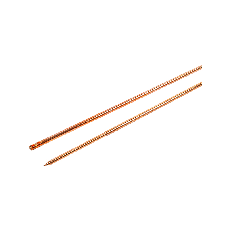
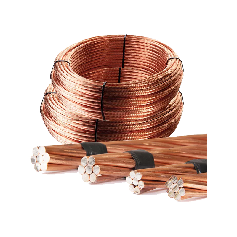
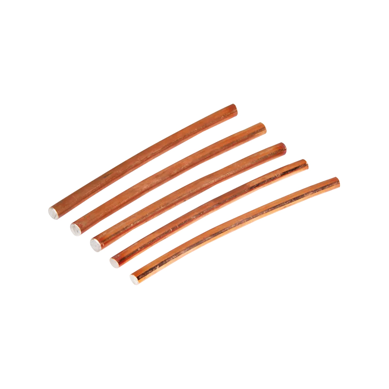
| Copper-bonded steel | Steel core with copper layer | General-purpose industrial grounding | Combines conductivity with mechanical strength |
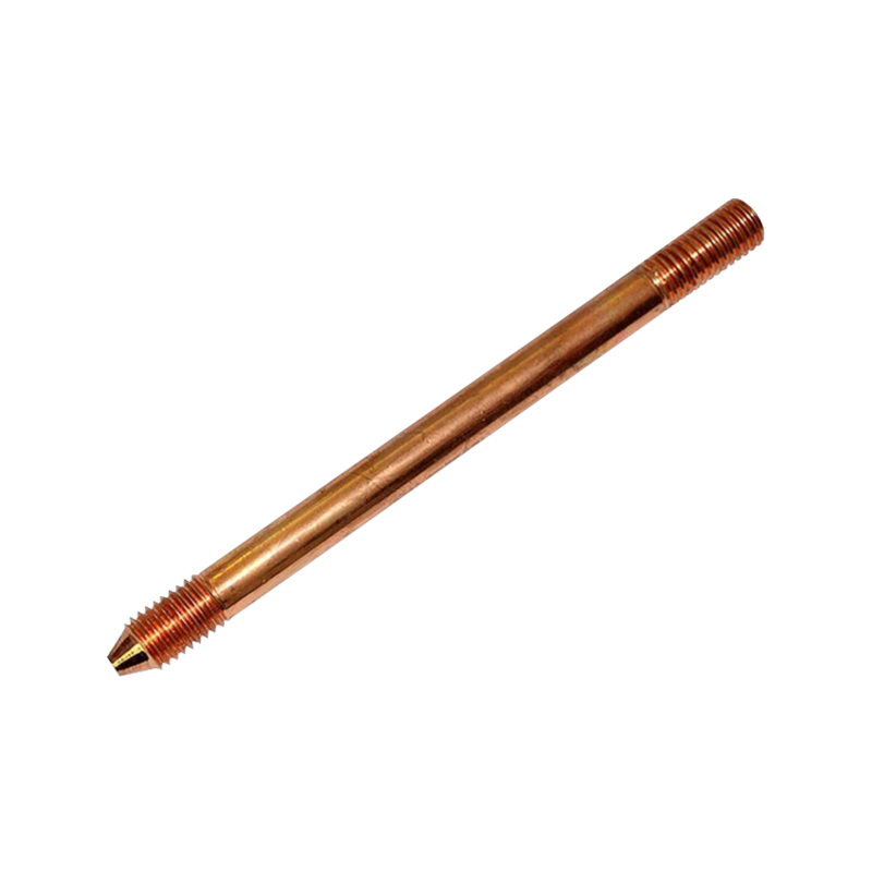
| Pure copper | Solid copper | High-conductivity and low-resistance requirements | Higher material cost and softer metal |
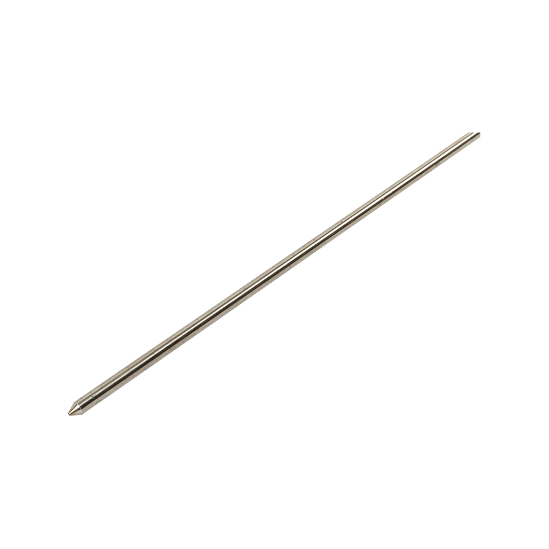
| Stainless steel | Solid stainless steel | Aggressive or contaminated soils | Longer service life in harsh conditions |
| Galvanized steel | Steel with zinc coating | Low-cost grounding and temporary works | Coating can be consumed over time |
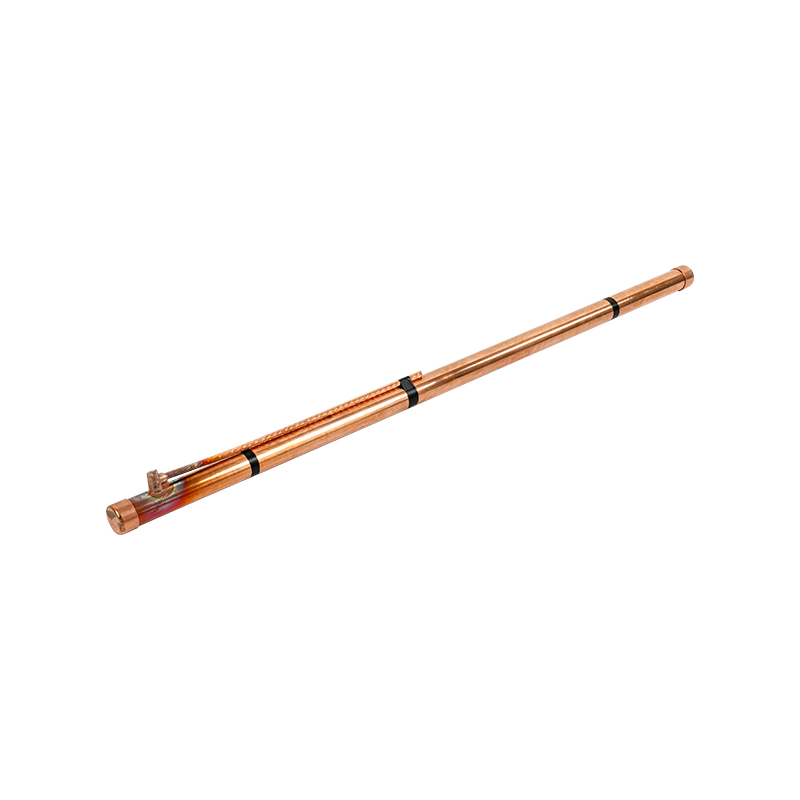
| Chemical earthing rod | Copper or steel electrode with conductive filler | High-resistivity soil or limited installation space | Requires proper backfill and periodic inspection |
For a standard industrial installation, the copper-bonded steel earthing rod is a strong default because the steel core gives the mechanical strength needed for driving, while the copper layer provides low electrical resistance and good corrosion performance in most soils. The choice becomes more specific when soil resistivity, coating thickness, and connection materials are added to the evaluation.
How to Choose the Right Earthing Rod for Your Project
Selection starts with a soil survey, not with the rod catalogue. Measure the soil resistivity in the actual installation zone, because values can range from less than 50 ohm-meters in wet clay to more than 1,000 ohm-meters in sandy or rocky ground. This figure influences rod length, rod quantity, rod spacing, and whether you need additional treatment.
Local codes and project specifications often set a target earth resistance. In some regions, a single rod is accepted when its measured resistance is 25 ohms or less, and a second rod is required if it is higher. Many industrial and telecommunication specifications tighten the limit to 10 ohms or less, while data centres and substations may call for 1 to 5 ohms. The correct approach is to compare the soil data with the specification before deciding whether one rod, several rods, or a chemical earthing rod is needed.
- Soil resistivity below 100 ohm-meters: standard copper-bonded or galvanized rods are usually sufficient.
- Soil resistivity between 100 and 500 ohm-meters: a longer rod or multiple rods spaced apart are common.
- Soil resistivity above 500 ohm-meters: consider parallel rods, deep-driven rods, or a chemical earthing rod to bring the resistance down.
Corrosion risk changes the material choice. A copper-bonded rod works well in many neutral soils, but an installation near the coast, in an industrial site with chemical spill potential, or in highly acidic ground may require a pure copper earthing rod or a stainless steel alternative. Check the copper coating thickness on copper-bonded rods; 0.254 mm is a common specification, and a thinner layer can reduce service life in aggressive soil.
Installation Practices That Make a Difference
A properly selected earthing rod can still fail if the installation is rushed. The main risks are poor soil contact, bending during driving, an underrated clamp, and a connection that corrodes after the trench is closed. These risks are avoidable with well-established installation steps.
- Verify the location, soil resistivity, and target rod depth before driving. If the ground is rocky, use a pilot hole or install a longer rod in a trench rather than forcing the rod.
- Drive the rod vertically, keeping the driving tool aligned with the rod axis to avoid bending. The top of the rod should remain accessible and protected by an inspection cover if required.
- Use couplers when a sectional rod is needed to reach depth. A mechanical coupler should be compatible with the rod diameter and must create a low-resistance joint.
- Connect the earthing conductor with a clamp, connector, or exothermic weld that is rated for the conductor size and the rod finish. Galvanic corrosion can occur when incompatible materials are connected, so select appropriate rod couplers and clamps for the specific rod material.
- Measure the earth resistance after installation and again after the soil has settled or after a wetting cycle. If the value is too high, add another rod or improve the soil around the electrode.
When the earth resistance of a standard driven rod is still too high, a chemical earthing rod can be installed with a conductive backfill compound. This approach reduces the resistance over a larger soil volume, which is especially useful on cramped sites, gravel ground, or rocky locations where load-bearing rods cannot be driven deep enough.
Testing, Maintenance, and Long-Term Performance
Ground resistance is not a fixed number. It rises when the soil dries out, falls when rain raises moisture content, and can climb permanently when a connection corrodes or a coating is eaten away. A ground resistance test performed with a four-point or clamp-on tester gives the equipment owner a clear check of whether the earthing rod still meets the project specification.
For permanent installations, test at least once per year and after major events such as lightning storms, excavation near the rod, or changes in the nearby utility infrastructure. Keep a log of measured values so abnormal increases can be caught before they cause equipment damage. In high-frequency or electronic systems, inspect the connection between the rod and the earthing conductor as carefully as you inspect the rod itself; a loosened clamp creates an inductive and resistive obstacle that cannot be seen from the surface.
Good earthing design does not end with one driven rod. Multiple rods can be connected in parallel to lower resistance, and each additional rod should be spaced at least the length of a rod away from the first to avoid overlapping resistance areas. These rods need to be joined with continuous conductor and permanent connections, not with temporary wire twisted around the rod.
 About Us
 +86-15167536268
 29, Xingmei Avenue, Xinchang, Zhejiang, China