

 English
 简体中文
简体中文
A maintenance engineer at a 110 kV substation wants to verify the earth resistance of a newly connected ground electrode. The joint is buried under finished grade, so a simple test can turn into excavation, backfilling, and surface repair. A grounding inspection pit prevents this. It is a buried enclosure that keeps the connection and test point accessible while protecting them from soil, mechanical load, and accidental damage.
What Is a Grounding Inspection Pit?
A grounding inspection pit, also called an earthing inspection pit or ground inspection well, is a specially designed box installed at grade level around a critical point in the earthing system. The cover can be opened without digging, which gives the maintenance team immediate access to a test link, a bolted connection, or a conductor joint.
The main function is not just storage. A well-designed pit creates a stable inspection and testing point that can be used for years. It also changes the way maintenance is done. Instead of excavating to find a joint, the team opens the cover, connects an earth tester, takes a reading, and closes the cover again.
Why a Grounding Inspection Pit Is More Than a Box
An earth electrode may perform well on the day it is installed, but the surrounding soil moves, moisture changes, bolted connections loosen, and nearby excavation can damage a buried conductor. When a splice is hidden under concrete, these problems stay invisible until a fault occurs.
The pit is therefore a safety component. It provides a defined location where the continuity and resistance of the earthing path can be verified. Routine ground resistance measurement is common in industrial and utility installations, and a proper access point makes the test practical. The alternative is to assume that a buried joint is still good, which is not a reliable engineering assumption.
Types of Grounding Inspection Pits
There is no single pit for every job. The right choice depends on traffic load, site environment, the number of conductors, and how often the point must be accessed.
Concrete Grounding Inspection Pit
When a project requires high structural strength, a concrete grounding inspection pit is the standard option. It is commonly used in substations, transformer yards, industrial plants, and rail traction areas where vehicle loading or heavy maintenance equipment may cross the pit. The concrete body provides a rigid enclosure, and the cover is selected according to the expected load. For projects that need a tested, heavy-duty enclosure, the concrete grounding inspection pit is designed to meet this role.
Weak-Current Grounding Inspection Pit
For telecommunication rooms, instrument systems, fire alarm loops, and other low-energy earthing networks, the concern is not high fault current alone. Signal ground integrity, clean reference points, and cable separation matter. The weak-electricity grounding inspection pit is a compact solution that suits these systems. It provides dedicated cable entry and internal space for low-voltage grounding conductors while keeping signal and power circuits separated in a controlled way.
Light-Type Grounding Inspection Pit
Not every pit sits in a vehicle lane. For walkways, landscaped areas, temporary facilities, or locations where installation speed matters, a light-type grounding inspection pit reduces the load on the foundation and makes handling easier. Because it is usually made from a lightweight but corrosion-resistant composite material, it is also less likely to crack from minor soil settlement. The light-type grounding inspection pit is a practical option when structural requirements are moderate and installation efficiency is important.
| Type | Best Suited For | Key Selection Cue |
|---|---|---|
| Concrete | Substations, transformer yards, industrial plants, heavy traffic areas | High mechanical strength and stability under load |
| Weak-current | Telecommunications, instrumentation, fire alarm and signal grounding | Compact dimensions and dedicated cable entry |
| Light-type | Walkways, landscaped areas, temporary sites, low-load zones | Fast installation, easy handling, corrosion resistance |
Design and Installation Points That Affect Long-Term Performance
Even a well-manufactured pit will fail early if the base is not stable or the cover is not matched to the load. The following design points should be considered before concrete is poured.
- Confirm the maximum vehicle load that can pass over the pit. A pedestrian cover is not safe under a forklift or maintenance truck.
- Position the pit so that the test point and cable terminals are near the top of the internal space. A technician should not have to climb in or use a mirror to reach them.
- Arrange the conductors with slack. Soil movement can pull on a cable that is stretched across the pit, damaging the connection over time.
- Provide drainage or a sealed cover depending on the site. Water inside the pit speeds up corrosion and makes resistance testing less accurate.
- Backfill around the body carefully. Voids under or around a pit cause settlement and create a trip hazard at the cover.
How an Inspection Pit Fits Into the Earthing Network
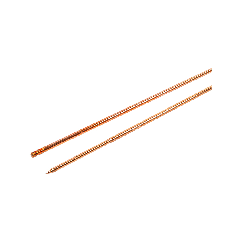
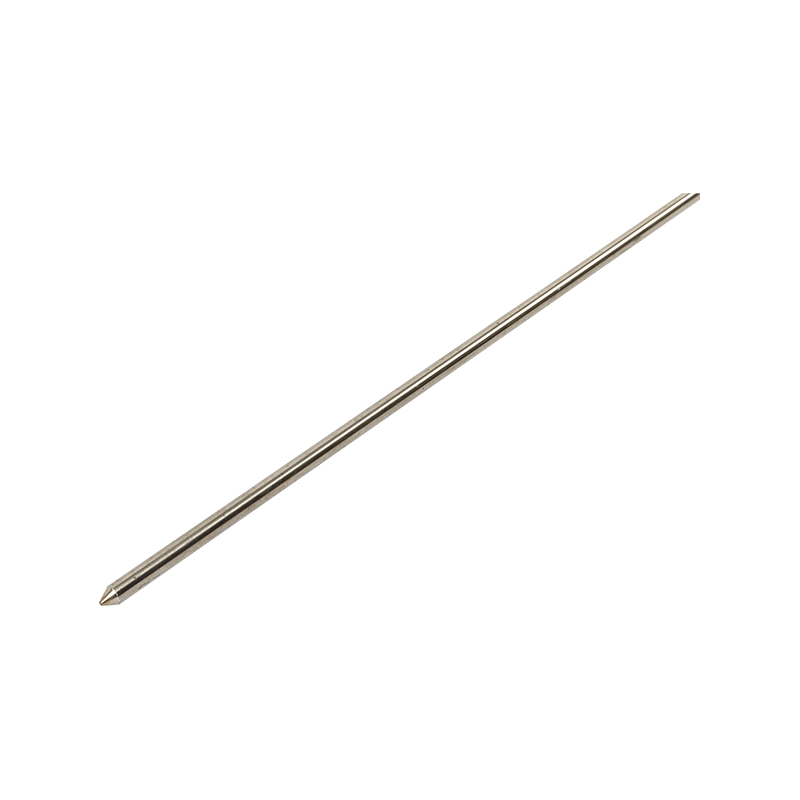
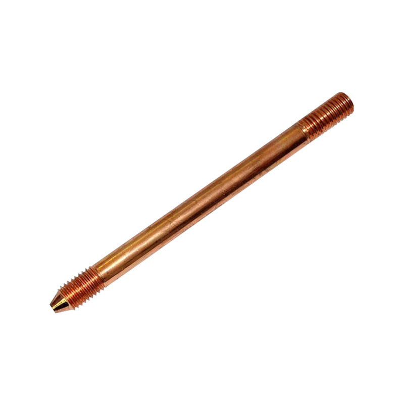
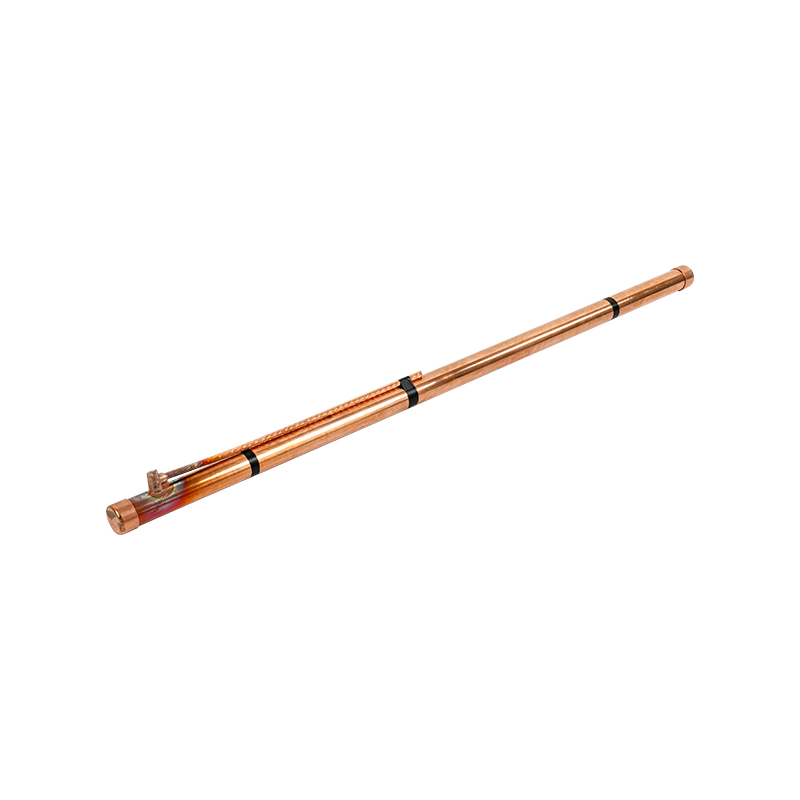
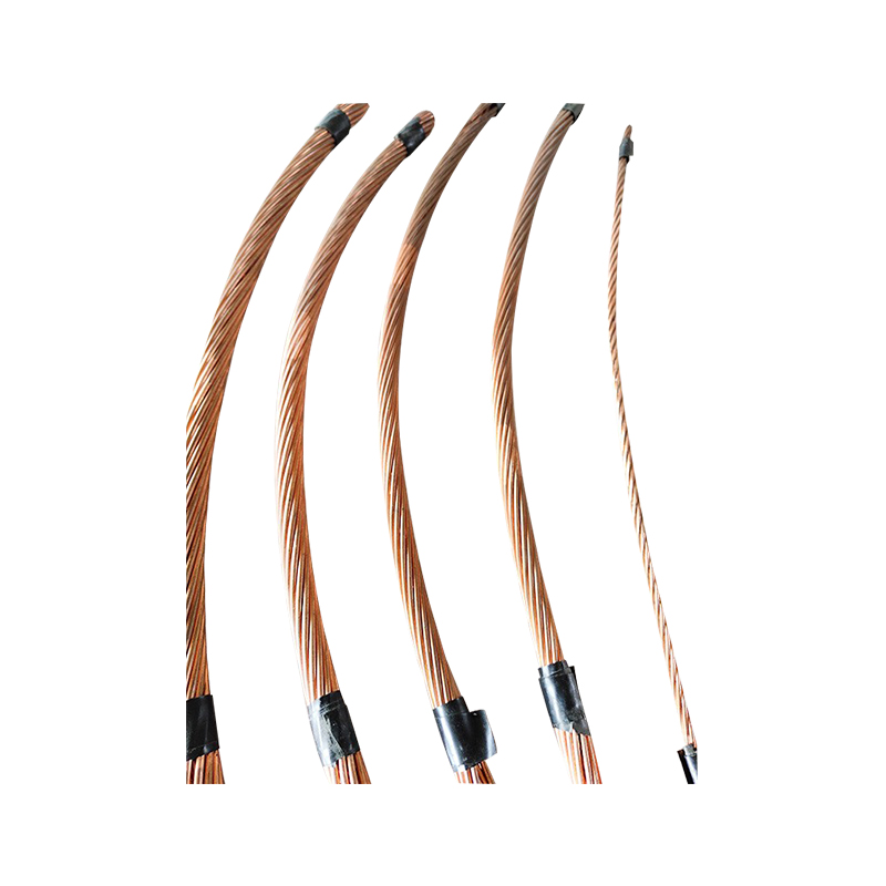
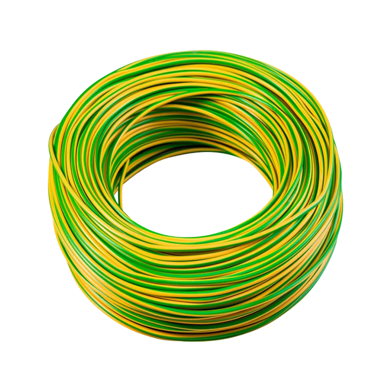
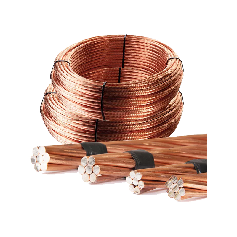
An earthing network is more than a single rod. The buried grounding rods are driven into the soil to achieve the target resistance. Grounding conductors connect the equipment, panels, and lightning protection system to the electrode field. These parts are joined by clamps, connectors, or exothermic welds.
The grounding inspection pit is the access point that ties these components to the maintenance plan. It is usually installed where an earth conductor meets a ground electrode, where a bonding busbar is mounted, or where several down conductors are interconnected. In a lightning protection system, the pit also provides a convenient place to make a testable link.
Grounding Inspection Pit Selection Checklist
When you evaluate a grounding inspection pit for a project, focus on documented dimensions, material properties, and installation conditions rather than generic product names.
- Check the internal usable space, not only the outer diameter, because large conductors need bending room.
- Ask for the cover's load rating and confirm it is based on the wheel load of the largest vehicle on site.
- Match the pit material to the soil chemistry. Sulfate-rich or chloride-contaminated soil is more aggressive to ordinary concrete and mild steel.
- Confirm that the pit can accept a test link, busbar, or grounding clamp if the connection point is meant to be moved or isolated.
- Consider the installation sequence. A pit that is delivered too late may force the contractor to rebuild part of the earth electrode system.
Inspecting and Testing Through the Pit
Once the pit is in service, it should become part of a routine schedule. Open the cover and look for signs of water, condensation, corrosion, or mechanical damage. Clean the interior if debris has collected. Tighten bolted connections that have drifted from their specified torque, and inspect the conductor for discoloration, cracks, or broken strands.
Resistance testing should be performed using the same method and instrument each time, so that readings can be compared with the baseline. Record the values and keep them with the site's electrical maintenance history. If a reading changes sharply from one test to the next, the pit gives you a direct place to investigate the cause before the problem becomes a fault.
Final Recommendation
Choose a grounding inspection pit with the same discipline as the rest of the grounding system. Define the structural load first, then the access requirement, and then the maintenance plan. A manufacturer that can supply concrete, weak-current, and light-type pits, and also produce the grounding rods, conductors, clamps, and exothermic welding materials that go with them, makes it easier to keep the entire project consistent. A pit that is correctly selected, correctly installed, and regularly tested will protect the connection point for the life of the earthing system.
 About Us
 +86-15167536268
 29, Xingmei Avenue, Xinchang, Zhejiang, China