

 English
 简体中文
简体中文
Every grounding system tells a story about the soil it is buried in. A coastal substation may see the same copper-clad steel rod perform well for twenty years, while an identical rod in acidic clay can corrode far ahead of schedule. Project teams that compare only unit prices often discover this the hard way: the cheapest electrode is rarely the most economical one once it fails below a concrete slab or inside a backfilled trench.
The practical conclusion is that a grounding rod should be chosen for its operating environment, not just its price. Once you know the soil resistivity, the corrosivity of the site, the required service life, and the fault current duty, the material selection narrows down quickly.
Why Grounding Rods Matter
A grounding rod is the physical interface between an electrical system and the earth. Its job is to provide a low-impedance path for fault current, lightning current, and static charge to dissipate safely into the ground. Without a properly sized and correctly installed rod, the protective devices in a distribution board, a lightning protection network, or a telecommunication shelter cannot perform as intended.
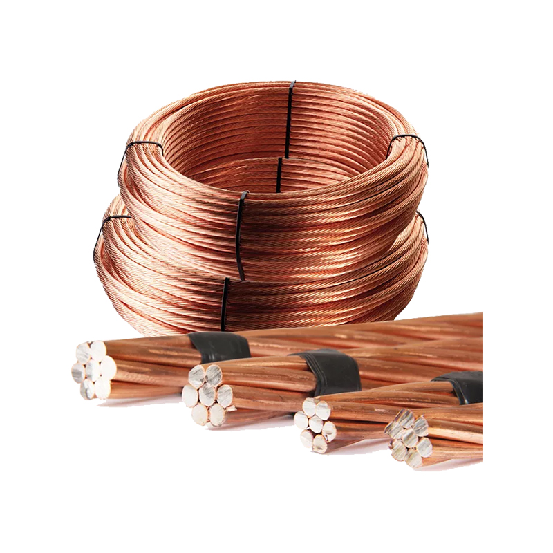
The rod works together with the rest of the earthing system: copper conductors carry current from equipment to the rod, clamps and exothermic welds create low-resistance connections, and inspection pits give maintenance crews access for testing. If the rod itself is poorly selected or installed, the performance of the entire earthing network is compromised.
Common Types of Grounding Rods
Several rod constructions dominate modern earthing practice. The grounding rod range covered by most project specifications includes five main types, each with a distinct balance of conductivity, corrosion resistance, mechanical strength, and cost.
| Rod type | Core material | Key advantage | Typical application |
|---|---|---|---|
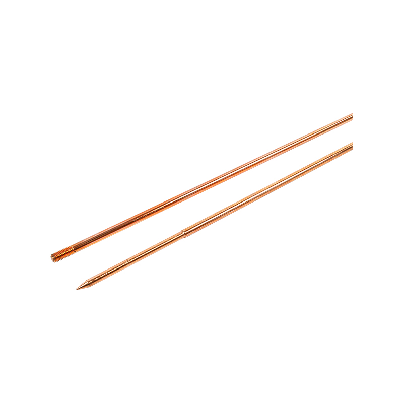
| Copper-clad steel | Steel core, copper bonded on the surface | High strength for deep driving, good conductivity, balanced cost | General substation, industrial and commercial earthing |
| Pure copper | Solid copper | Excellent conductivity and corrosion resistance | Highly corrosive soils or sites where maximum conductivity is required |
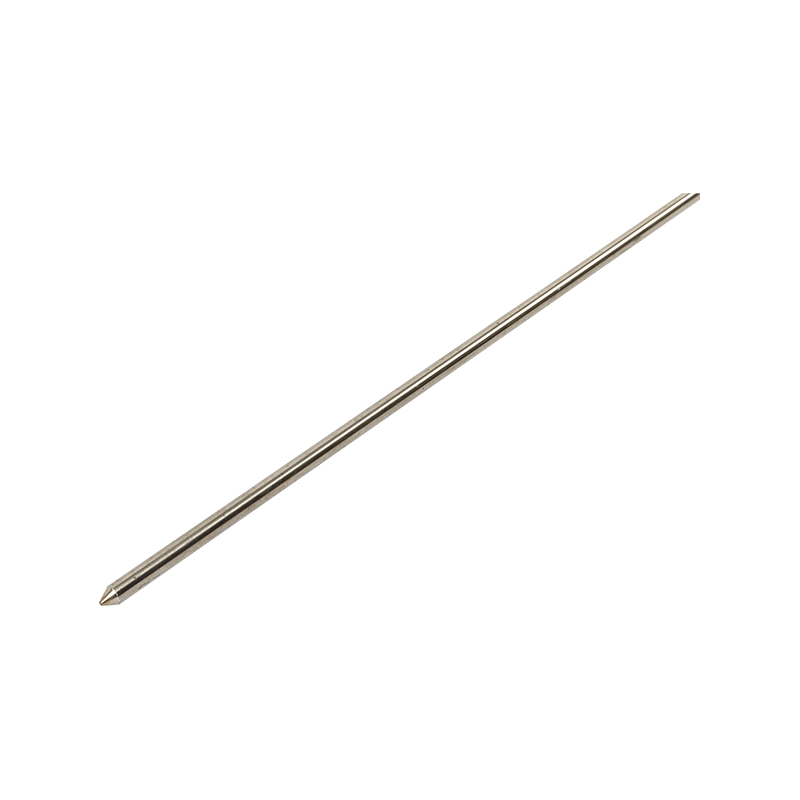
| Stainless steel | Solid stainless steel | Superior resistance to aggressive chemicals | Industrial plants, coastal areas, chemical environments |
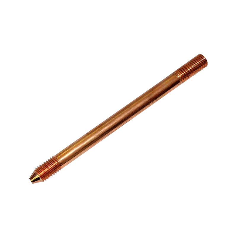
| Galvanized steel | Steel with zinc coating | Low cost and strong mechanical performance | Lower-grade or temporary earthing, specific utility requirements |
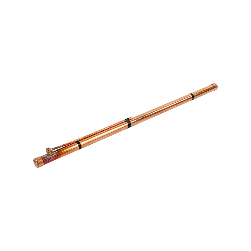
| Chemical or electrolytic | Copper tube with conductive backfill | Very low earth resistance in poor soil | High-resistivity soil, limited footprint sites |
For a closer look at the differences between electrode constructions, our technical article on types of grounding rods explains the performance trade-offs in more detail.
Copper-Clad Steel
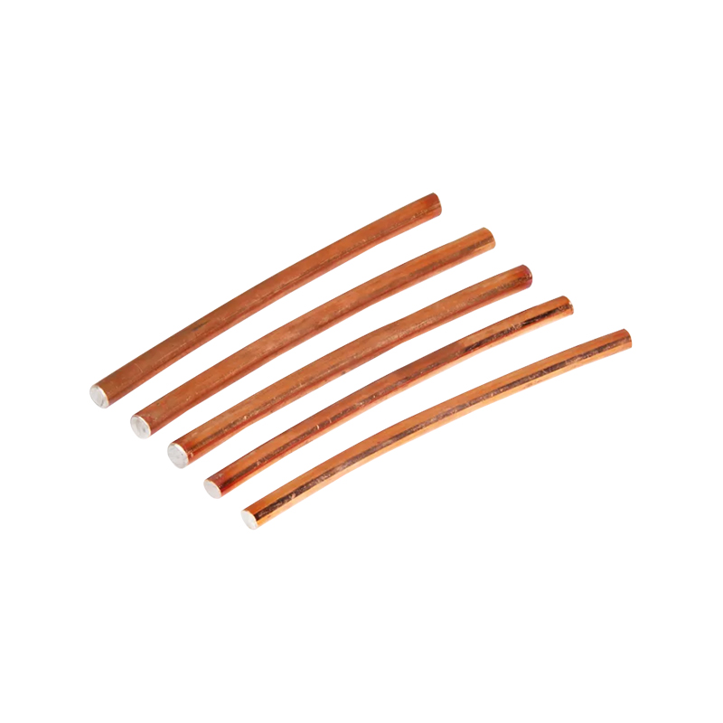
Copper-clad steel is the most widely specified type because the steel core provides the mechanical strength needed for deep driving, while the copper surface carries the current and resists corrosion. The bonded copper layer must be uniform and thick enough to survive installation and long-term service. For most projects, a copper-clad steel grounding rod is the most practical first choice.
Stainless Steel
Where the soil contains chlorides, acids, or other aggressive chemicals, stainless steel rods offer a longer service life than copper-bonded products. They are stiffer and harder to drive, but they resist pitting and surface corrosion in environments that would quickly attack other materials. Projects in coastal or industrial areas often specify stainless steel grounding rods for critical electrodes.
Chemical Grounding Rods
When the available ground area is small and the soil resistivity is high, a chemical rod is a practical solution. It consists of a copper electrode surrounded by a conductive backfill that absorbs moisture and lowers the resistance around the rod. This type is common in urban sites, transformer stations, and tower bases where conventional driven rods cannot reach the target resistance. A chemical grounding rod can sometimes achieve an acceptable resistance value with a single electrode in soil where several conventional rods would be required.
How to Choose the Right Grounding Rod
Selection starts with the soil and the performance target, not with the product catalogue. Once the site conditions are understood, the rod type, diameter, length, and quantity become clear.
Soil Resistivity and Corrosivity
Soil resistivity determines how easily current can spread into the ground. Low-resistivity soil such as clay or loam makes it easier to achieve a low earth resistance, while rocky or sandy soil requires longer rods, multiple rods, or chemical backfill. Corrosivity is a separate issue: the same soil can be highly conductive and highly corrosive at the same time. A soil analysis should check resistivity, pH, chloride content, and sulfate content before finalizing the rod material.
Service Life and Criticality
For a permanent substation or a railway signaling system, the rod must last as long as the asset it protects. Replacing an electrode under an operating substation is expensive and disruptive. For short-duration construction sites or mobile equipment, a lower-cost rod may be acceptable. The criticality of the connected equipment should drive the corrosion allowance and the connection method.
Standards and Performance Targets
Most projects specify a maximum earth resistance value, such as 10 ohms for substations or lower for sensitive electronic systems. The rod material should meet recognized product standards covering copper bond thickness, straightness, and tensile strength. Local electrical codes and the project specification will also define the required rod diameter and minimum length.
A practical selection sequence is:
- Measure or estimate soil resistivity across the site.
- Test soil corrosivity and review the required service life.
- Set the target earth resistance value from the project specification.
- Choose the rod material based on corrosion risk and conductivity needs.
- Determine rod length, diameter, and number of electrodes from the target resistance.
- Select the connection method and inspection access points.
Installation and Connection Considerations
Correct installation matters as much as material selection. A rod with an excellent copper bond can still perform badly if it is not driven to the right depth, if the connection corrodes, or if it is damaged during driving.
Rods should be driven vertically whenever possible so that the electrode reaches deeper, more stable soil layers. In shallow or rocky ground, multiple rods connected in parallel can reduce the total earth resistance. The spacing between parallel rods should be at least equal to the rod length so that the surrounding resistance zones do not overlap too much.
Connections are the most common source of long-term failure. Mechanical clamps are easy to inspect and replace, but they must be tightened to the correct torque and installed on a clean rod surface. Exothermic welding creates a permanent molecular bond that does not loosen or corrode over time, which makes it the preferred method for critical connections. Couplers are used to join rod sections when driving depth is limited by equipment access. After installation, the connection should be wrapped or protected according to the project specification to prevent corrosion at the soil surface.
For systems that require periodic verification, the electrode should be terminated in a grounding inspection pit instead of being buried directly. This gives maintenance crews a safe point to measure resistance and inspect the connection without excavating the surrounding soil.
Grounding Rods Across Industries
Grounding rods are used wherever electrical equipment must be safely connected to the earth. In power distribution networks, they form part of substation earthing grids and pole-mounted transformer electrodes. In high-speed rail, they protect signaling and traction power systems from fault currents and lightning. In petrochemical plants, they provide a stable reference plane for instrumentation and dissipate static charge in hazardous areas.
Solar farms and telecommunication sites are also heavy users of grounding rods. Photovoltaic arrays cover large areas and are exposed to lightning, while telecom shelters contain sensitive electronics that require a clean, low-noise earth reference. In every case, the rod selection follows the same logic: soil first, material second, and installation quality always.
Maintenance and Testing
A grounding electrode does not fail suddenly in most cases; its resistance rises gradually as corrosion, drying soil, or connection degradation take effect. Regular testing is therefore essential. The earth resistance should be measured after installation and then at scheduled intervals, typically annually for critical facilities or as defined by the asset owner.
If the measured resistance exceeds the target value, the first step is to inspect the visible connection and the rod head. A loose clamp or a corroded braid is easier to fix than an electrode problem. If the resistance remains high, additional rods can be driven in parallel or a chemical rod can be installed to lower the total resistance. Maintaining accurate test records helps identify trends before they become faults.
Sourcing Grounding Rods for Your Project
Grounding rod selection is an engineering decision, but it still depends on product quality and consistency. Copper-clad rods need a uniform bond thickness; stainless steel rods need clean material; chemical rods need controlled backfill quality. A manufacturer that supplies the full earthing chain can keep these parameters consistent across rods, conductors, clamps, and welding materials.
Xinchang TuAn Machinery Co., Ltd. manufactures grounding rods and the complete range of earthing components used with them. If you are specifying an earthing system and want to translate site conditions into a practical bill of materials, a conversation with an experienced grounding equipment manufacturer is a good starting point.
 About Us
 +86-15167536268
 29, Xingmei Avenue, Xinchang, Zhejiang, China