

 English
 简体中文
简体中文
Safeguarding industrial power distribution networks, telecommunication towers, electrical substations, and lightning protection networks against catastrophic insulation breakdowns requires low-impedance electrical discharge paths. High-integrity earthing fixing clamps serve as the primary mechanical and electrical connections needed to bond grounding conductors directly to vertical earth rods, horizontal tape matrices, and structural steel beams. By enforcing tight, high-pressure metallic contact interfaces, these specialized fastening assemblies guarantee that high-magnitude fault currents and atmospheric lightning surges are directed safely into the earth mass, preventing dangerous touch voltages from threatening personnel or destroying sensitive solid-state electronic systems.
Metallurgical Interfaces and Galvanic Corrosion Mitigation
The long-term safety and reliability of a grounding network depend directly on the metallurgy of the grounding clamps. Because these connectors are buried in damp, chemically active soils or exposed to harsh weather, selecting incompatible metals can cause rapid material breakdown, threatening the safety of the entire electrical system.
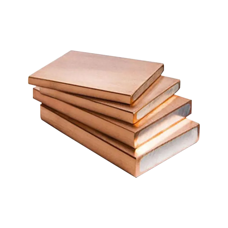
When two dissimilar metals—such as a copper grounding wire and a galvanized steel structural beam—are clamped together in the presence of soil moisture, they form a natural galvanic cell. The metal with the lower electrochemical potential acts as an anode and corrodes rapidly, forming an insulating layer of metal oxide across the connection. This oxidation layer restricts current flow, raising the joint's electrical resistance. To prevent this hazardous breakdown, industrial grounding networks utilize high-strength copper alloys like gunmetal, marine-grade aluminum-bronze, or specialized bi-metallic transition plates. These bi-metallic plates feature high-purity copper molecularly bonded to an aluminum base, allowing installers to connect copper grounding wires to aluminum or steel structures without triggering galvanic degradation.
Evaluating Mechanical Durability Across Key Grounding Material Profiles
Selecting the proper grounding clamp material requires evaluating the specific environmental conditions of the job site. High-purity copper clamps deliver exceptional electrical conductivity but are soft and can stretch over time if over-torqued. Heavy-duty stainless steel (Grade 316) connectors provide outstanding mechanical strength and resistance to acidic soils, but possess higher base resistance, requiring precision engineering to maximize surface contact areas. High-tensile brass or gunmetal alloys offer an ideal balance for underground grid connections, providing excellent resistance to underground corrosion while maintaining a stable, low-resistance electrical path across decades of service.
Fluid Analogy of Short-Circuit Current Dissipation Physics
During a major electrical fault or a direct lightning strike, an earthing clamp must handle massive surges of electrical energy, often exceeding 25 kilo-Amperes (kA) for a full second. Under these extreme conditions, the grounding connection acts like a high-pressure valve in a water plumbing network.
If the grounding clamp is loose or suffers from surface oxidation, the fault current faces an electrical bottleneck, known as high contact impedance. This constriction causes a massive drop in voltage across the tight junction, converting the blocked electrical energy into intense heat almost instantly. The temperature inside the connection can surge above 1085°C, which can melt copper conductors, shatter concrete foundation footings, and cause the grounding path to fail right when it is needed most. A professionally torqued, low-resistance clamp ensures the connection stays cool and handles the energy spike safely, letting the massive electrical surge flow smoothly into the earth grid.
Mechanical Classifications and Performance Metrics
Grounding engineers must carefully match the physical design of the fixing clamp to the specific shapes of the conductors being joined. Using a clamp designed for round rods on a flat metal tape reduces the physical contact area, which can cause the joint to overheat and fail during an electrical surge.
The table below outlines the standard mechanical dimensions, torque limits, short-circuit ratings, and primary applications for industrial earthing fixing clamps:
| Clamp Engineering Profile | Conductor Capacity Range | Installation Torque Target | Short-Circuit Capacity (1s) | Target Structural Environment |
|---|---|---|---|---|
| Rod-to-Cable G-Clamp (High-Strength Brass) | 16mm Rod / 16-70 $mm^2$ Cable | 12 Nm to 15 Nm | 14.2 kA Current Rating | Sub-surface earth rods, residential service entries |
| Square Tape Clamp (Gunmetal Alloy) | 25x3mm to 50x6mm Flat Tape | 18 Nm to 22 Nm | 25.0 kA Current Rating | Lightning protection down-conductors, factory perimeters |
| Heavy-Duty U-Bolt Clamp (Copper / Stainless) | 20mm Rod / 95-240 $mm^2$ Cable | 25 Nm to 30 Nm | 40.0 kA Current Rating | Utility substations, high-voltage transformer bays |
Surface Micro-Topography and Contact Resistance Mechanics
To the naked eye, a polished copper grounding bar and the jaw of a heavy fixing clamp look perfectly flat. However, viewing these metal parts under a microscope reveals a jagged terrain filled with microscopic peaks and valleys, known to materials engineers as surface asperities.
When a clamp is loosely tightened over a conductor, the two pieces of metal only touch at their highest microscopic peaks. This limited contact area represents less than 5% of the total physical surface area of the joint, forcing all electrical current to squeeze through a few tiny points. To ensure maximum safety and performance, installers must apply high mechanical torque to the clamp bolts. This intense physical pressure crushes the microscopic peaks together, flattening the metal surfaces and expanding the actual contact area. This reduces the contact resistance down to under 50 micro-Ohms, allowing large fault currents to flow through the joint smoothly without overheating.
The Essential Role of Anti-Oxidant Compounds
Even when clamped under high pressure, the microscopic valleys between the metal surfaces can still trap air and moisture, leading to internal corrosion over time. To seal these gaps, professional installers apply a thick layer of conductive anti-oxidant grease filled with suspended zinc or copper particles across the metal surfaces before assembling the clamp. As the bolts are torqued down, this specialized grease squeezes into the open valleys, blocking air and moisture out while creating parallel electrical paths that optimize current flow through the joint.
Step-by-Step Field Installation Sequence for Structural Steel Bonding
Connecting a heavy copper grounding wire to a building's main structural steel column requires following precise, structured installation steps. Proper preparation ensures the grounding connection maintains clean, low-resistance metal-to-metal contact that can handle high electrical faults safely for decades.
- Strip Protective Surface Coatings: Use an electric die grinder or a stiff wire wheel brush to grind away all paint, primer, scale, and rust from the target area on the structural steel beam. The metal must be cleaned down to a bright, shiny steel finish to ensure there are no insulating layers between the beam and the clamp.
- Apply Conductive Protective Compound: Coat the freshly ground steel surface and the jaws of the fixing clamp immediately with a generous layer of synthetic, zinc-filled anti-oxidant grease. This protective layer seals the raw steel away from oxygen, preventing surface rust from forming before the connection can be bolted together.
- Position Conductor and Align Clamp Jaws: Lay the bare, clean copper grounding wire inside the designated channel of the fixing clamp. Slide the clamp assembly over the prepared flange of the steel beam, making sure the conductor matches the alignment grooves perfectly to avoid pinching or kinking the wire.
- Execute Alternating Torque Tightening: Thread the high-tensile fasteners into the clamp body by hand. Use a calibrated click-type torque wrench to tighten the bolts in an alternating pattern, gradually ramping up the pressure until reaching the engineering target of 22 Nm for standard M10 hardware, ensuring even clamping pressure across the entire joint.
- Seal Joint with Weatherproof Barriers: Wipe away any excess grease that squeezed out during tightening. Wrap the completed clamp assembly tightly in a heavy layer of self-amalgamating rubber tape or apply a thick coat of protective bitumen compound, completely sealing the connection away from rain, air, and environmental chemical hazards.
Root Cause Defect Diagnosis and Field Performance Audits
When a facility's routine maintenance check reveals a rise in grid resistance or a localized grounding fault, technicians can locate and correct the mechanical issue by analyzing the physical condition of the connection hardware.
A common field issue is a loose, rattling connection accompanied by pitting or arc-burn scars across the clamp jaws. This mechanical failure is typically caused by thermal cycling strain combined with a lack of spring washers during initial assembly. As seasonal power shifts warm and cool the grounding wires, the metals expand and contract at different rates, causing the bolts to slowly back out over time. The resulting air gaps allow tiny electrical arcs to jump across the loose joint during everyday static discharges, pitting the metal surfaces and increasing resistance. To resolve this, technicians must cut away the damaged wire ends, grind the clamp surfaces smooth, and reassemble the joint using high-durability Belleville spring washers that maintain constant tension through years of temperature changes.
Another frequent fault discovered during field audits is a complete mechanical break along the body of cast brass clamps buried underground. This structural failure typically points to stress corrosion cracking caused by over-torquing during installation. If an installer ignores torque specs and uses a long cheater pipe on a standard wrench, they can over-tighten the bolts, creating massive internal stress within the cast brass body. When exposed to winter freeze-thaw cycles and naturally occurring ammonia in the soil, the stressed brass cracks and splits apart, breaking the ground path. Maintenance teams must replace the broken hardware with heavy-duty, hot-forged copper alloy clamps, using digital torque wrenches to ensure the fasteners are tightened within safe engineering limits.
 About Us
 +86-15167536268
 29, Xingmei Avenue, Xinchang, Zhejiang, China