

 English
 简体中文
简体中文
An electrical contractor is terminating a 200 A feeder that runs more than 150 feet to a new production line. The breakers are in place, the phase conductors are pulled, and the ground wire is the last item on the drawing. It is also one of the most frequently misapplied items on the job. The ground wire ampacity chart supplies the direct answer: for a 200 A overcurrent device, the minimum equipment grounding conductor is 6 AWG copper or 4 AWG aluminum. That answer carries one qualification, covered later in this article, because long runs that force larger phase conductors also force a larger ground wire.
What a Ground Wire Ampacity Chart Actually Tells You
An ampacity chart for grounding conductors does not work like an ampacity chart for power conductors. A conductor that carries load is sized by continuous current and insulation temperature rating, while an equipment grounding conductor (EGC) carries current only during a fault and only until the overcurrent device clears it. The minimum EGC size is therefore set by the rating of the upstream overcurrent protection device, not by the connected load and not by the length of the run.
The ground wire ampacity chart is a simplified presentation of NEC Table 250.122. The table pairs each standard overcurrent device rating with the smallest copper and aluminum EGC permitted ahead of that device. A 60 A breaker calls for 10 AWG copper; a 100 A breaker calls for 8 AWG copper. The reasoning is straightforward: larger fault currents heat the conductor more quickly, so the EGC must be heavy enough to carry the worst-case fault current until the breaker or fuse opens.
One caution applies before you use the chart. This is the table for equipment grounding conductors, not for grounding electrode conductors (GECs). A GEC bonds the grounding electrode, such as a ground rod or a concrete-encased electrode, to the service, and it is sized from Table 250.66 using the service conductor size, not the overcurrent device rating. Mixing up these two tables is one of the most common grounding design errors in the field.
Ground Wire Ampacity Chart: Minimum Equipment Grounding Conductor Sizes
The complete chart for equipment grounding conductors, based on the rating of the automatic overcurrent device ahead of the equipment, is shown below.
| Overcurrent device rating (A) | Copper EGC (AWG or kcmil) | Aluminum or copper-clad aluminum EGC (AWG or kcmil) |
|---|---|---|
| 15 | 14 AWG | 12 AWG |
| 20 | 12 AWG | 10 AWG |
| 60 | 10 AWG | 8 AWG |
| 100 | 8 AWG | 6 AWG |
| 200 | 6 AWG | 4 AWG |
| 300 | 4 AWG | 2 AWG |
| 400 | 3 AWG | 1 AWG |
| 500 | 2 AWG | 1/0 AWG |
| 600 | 1 AWG | 2/0 AWG |
| 800 | 1/0 AWG | 3/0 AWG |
| 1000 | 2/0 AWG | 4/0 AWG |
| 1200 | 3/0 AWG | 250 kcmil |
| 1600 | 4/0 AWG | 350 kcmil |
| 2000 | 250 kcmil | 400 kcmil |
| 2500 | 350 kcmil | 600 kcmil |
| 3000 | 400 kcmil | 600 kcmil |
| 4000 | 500 kcmil | 800 kcmil |
| 5000 | 700 kcmil | 1000 kcmil |
| 6000 | 800 kcmil | 1200 kcmil |
In everyday installations, the rows from 15 A to 600 A cover most branch circuits and feeders. The higher rows apply to large industrial services and switchgear, where the EGC becomes a substantial cable in its own right. Whatever the row, the conductor sizes listed are the minimum permitted; larger conductors are always allowed.
Copper vs. Aluminum: Reading the Columns
Copper and aluminum are listed as separate columns for a reason. Copper has a conductivity close to 100 percent IACS, while aluminum sits around 61 percent IACS. The aluminum EGC therefore has to be larger for the same fault-current capacity. For a 200 A feeder, the copper EGC is 6 AWG and the aluminum EGC is 4 AWG; at 600 A the gap widens to 1 AWG copper versus 2/0 AWG aluminum.
The AWG scale is easy to misread because the numbers run backwards. A 14 AWG conductor is smaller than an 8 AWG conductor, and 4/0 AWG is the largest stranded size before the scale switches to kcmil, where the number expresses thousands of circular mils. Once you are used to the scale, the relationship between the copper and aluminum columns stays consistent from the top of the table to the bottom.
Aluminum and copper-clad aluminum EGCs are permitted in most installations, but they come with two practical conditions. The terminations must be listed for aluminum conductors, and in damp environments the manufacturer's recommended antioxidant treatment should be applied. These details are easy to miss on a material takeoff, and they are a frequent source of loose, deteriorated connections in older grounding systems.
When the Chart Is Not Enough: Voltage-Drop Upsizing
Circuit conductors are routinely oversized on long runs to limit voltage drop, and that changes the ground wire calculation. NEC 250.122(B) requires the equipment grounding conductor to be increased proportionally when the ungrounded conductors are increased in size. The reason is that the ground-fault path has also become longer; the EGC must keep enough capacity to carry the fault current all the way back to the source so the overcurrent device can operate.
A short example makes the adjustment concrete. A 100 A circuit normally uses 3 AWG copper phase conductors and an 8 AWG copper EGC. If voltage drop forces the phase conductors up two AWG sizes to 1 AWG, the EGC also moves up two sizes, from 8 AWG to 6 AWG.
| Condition | Phase conductors | Equipment grounding conductor |
|---|---|---|
| Original 100 A design | 3 AWG copper | 8 AWG copper |
| After voltage-drop upsizing | 1 AWG copper | 6 AWG copper |
Because AWG sizes follow a geometric progression, shifting the EGC by the same number of AWG sizes keeps the cross-sectional ratio close to the original design. For adjustments that cross from AWG into kcmil values, compare the circular mil areas and resize the EGC by the same ratio.
Sizing Steps and Common Mistakes
Applying the chart correctly takes five steps, and each step has a known failure mode.
- Identify the overcurrent device rating. Use the ampere rating printed on the breaker or fuse, not the load the circuit is expected to carry.
- Find the matching row in the chart. If the exact rating is not listed, use the next higher rating.
- Choose the copper or aluminum column. The material column must match the EGC material you plan to install.
- Apply the voltage-drop adjustment. If the phase conductors were upsized, increase the EGC in the same proportion.
- Confirm the EGC is not larger than the phase conductors. The code does not require an EGC larger than the circuit conductors it protects.
- Sizing from the load instead of the protective device. A 200 A panel running at 120 A still requires the row for 200 A.
- Applying the wrong table. The grounding electrode conductor is sized by the service conductors, not by the overcurrent device.
- Skipping the voltage-drop adjustment on long feeders, which leaves the EGC undersized for the actual circuit length.
- Installing an aluminum EGC on connectors rated only for copper, which invites galvanic corrosion and loose joints.
Applying the Chart to Real Grounding Conductors
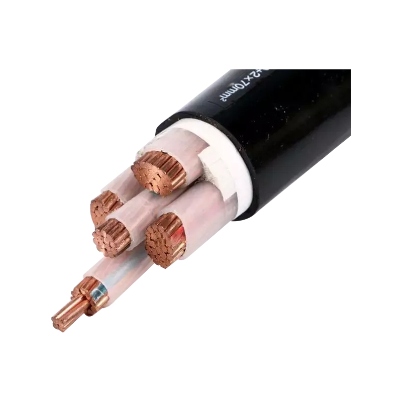
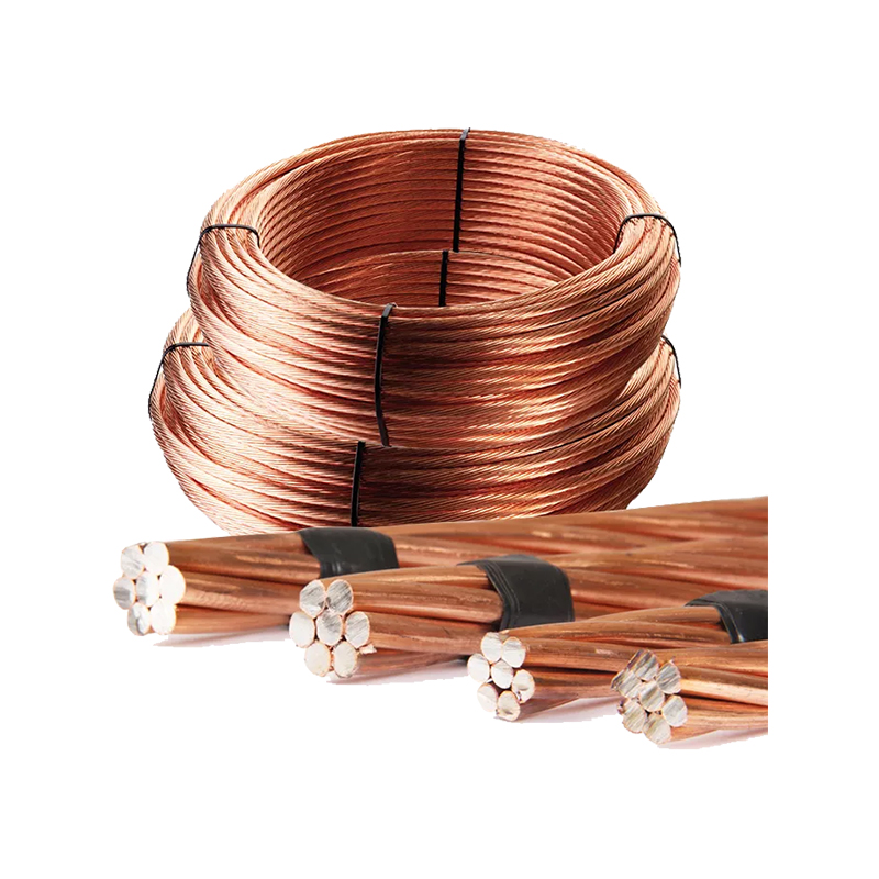
The chart establishes a minimum cross-section, but the material and construction of the grounding conductor decide whether the circuit stays healthy for the life of the installation. Stranded copper is the baseline for equipment grounding conductors: it pulls easily through conduit, resists corrosion in most environments, and terminates cleanly on lugs, clamps, and busbars. Contractors and engineers usually find these conductors listed across the grounding conductor range in the AWG and kcmil sizes shown in the chart, which makes matching the table row to a real product straightforward.
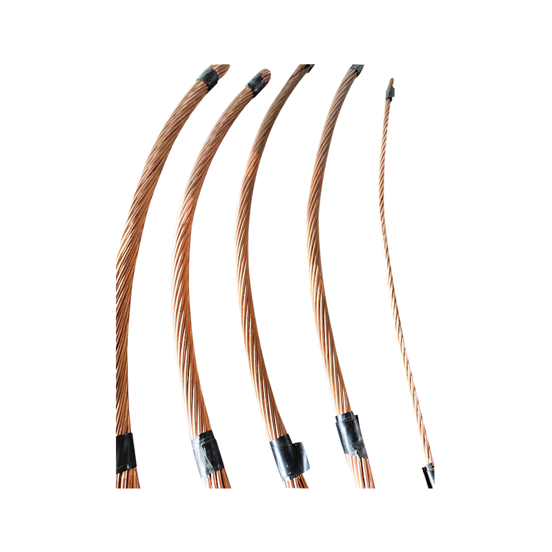 Stranded Copper Earthing Conductor for Grounding SystemsPure copper stranded wire suited for equipment grounding conductors. Its flexibility and corrosion resistance make it easy to pull through conduit and terminate on lugs or busbars, matching the cross-section sizes referenced in the sizing chart.View Product →
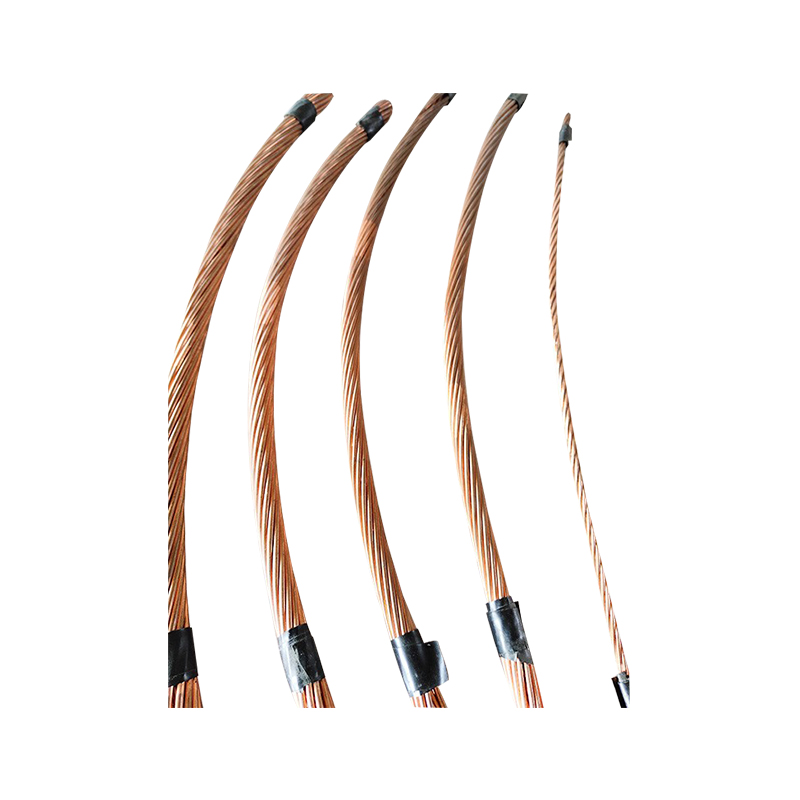
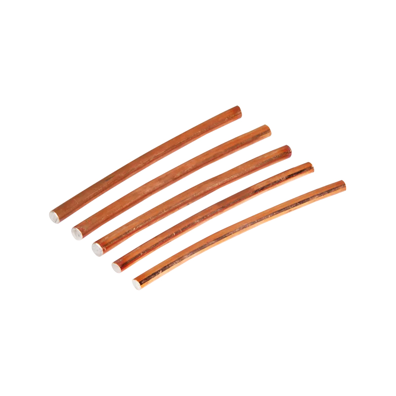
Copper-clad steel stranded wire is the standard answer for direct-burial grounding conductors and ground grid connections. The steel core provides the tensile strength needed to survive backfilling and soil movement, while the copper layer keeps surface resistance low. It is a practical choice where conductors are embedded rather than pulled into conduit, and where mechanical damage is the main risk to the grounding path.
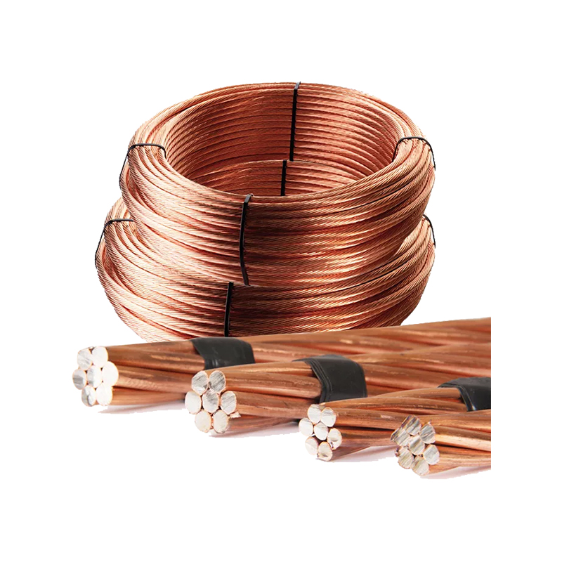 Copper-Clad Steel Stranded Wire for Direct-Burial GroundingThis stranded conductor combines a steel core with a copper cladding for high tensile strength and lower material cost. It resists mechanical damage and corrosion, making it a durable option for ground grids and embedded connections.View Product →
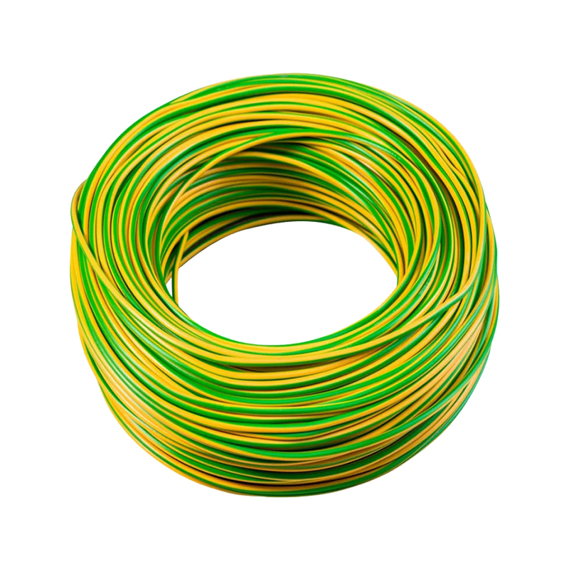
When a grounding conductor runs through chemically aggressive soil, concrete slabs, or areas where physical abrasion is a concern, an insulated conductor adds a protective layer. PVC-insulated copper stranded wire keeps the copper core clean and makes the conductor easy to identify during inspection, so continuity checks and maintenance planning become simpler over the long term.
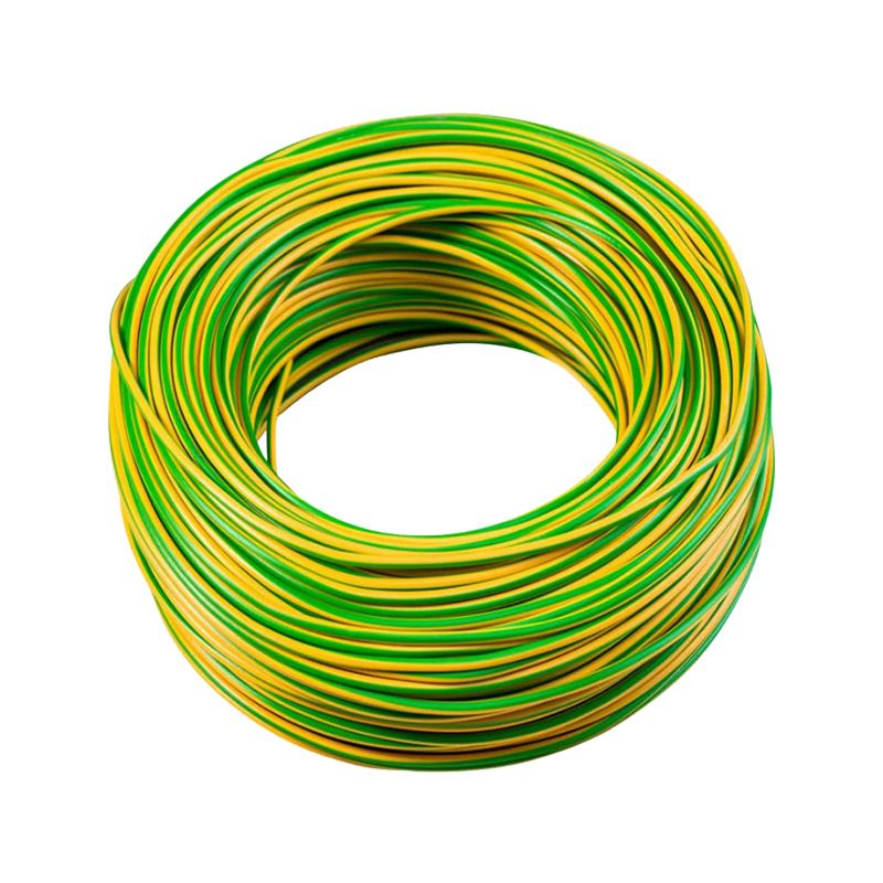 PVC-Insulated Stranded Copper Wire for Protected GroundingOxygen-free copper strands with a flame-retardant PVC insulation provide abrasion resistance and easy identification. Suitable for concealed or chemically aggressive environments, this flexible wire maintains clean continuity and simplifies inspection and maintenance.View Product →
Whichever material is selected, the installation still has to stay within the chart and within the termination rules for that conductor material. A grounding conductor is only as good as its end-to-end continuity; loose clamps, corroded lugs, and undersized jumpers undo the work done at the sizing stage. The practical side of maintaining continuity and low impedance in a grounding conductor comes back to the same principle: fault current has to flow from the fault point back to the source without interruption, or the overcurrent device will not open.
The ground wire ampacity chart is the fastest way to size an equipment grounding conductor, but it rewards people who understand the logic behind it. Identify the overcurrent device rating, find the correct row, pick the material column that fits the site conditions, and apply the voltage-drop adjustment when the phase conductors have been upsized. Size alone does not make a ground; the conductor still needs proper terminations, mechanical protection, and a continuous low-impedance path from the equipment back to the source. Applied that way, the chart delivers what it promises: a grounding conductor that carries fault current reliably and clears the protective device every time it is called on to do so.

 About Us
 +86-15167536268
 29, Xingmei Avenue, Xinchang, Zhejiang, China