

 English
 简体中文
简体中文
A crew drives two 8-foot ground rods, clamps the grounding electrode conductor to one rod, and calls it done. The electrical inspector red-tags the job because the second rod was never bonded to the first with a listed irreversible connector. That single missing bond is one of the most common NEC 250 violations, and it has nothing to do with how deep the rods went.
Article 250 of the National Electrical Code governs grounding and bonding. It is not one rule. It is a system of requirements covering electrode selection, conductor sizing, connection methods, and fault-current performance. Most failed inspections trace back to three decisions: which electrodes must be bonded together, what size grounding electrode conductor is required, and how each connection is made and protected. Get those three right, and the rest of Article 250 becomes documentation and detail.
What NEC 250 Actually Requires
NEC 250 is organized into parts. Part I sets general requirements. Part II covers system grounding. Part III covers the grounding electrode system and grounding electrode conductor. Part IV covers enclosure, raceway, and service cable connections. Part V covers bonding. Part VI covers equipment grounding and equipment grounding conductors. Part VII covers methods of equipment grounding. Part VIII covers direct-current systems. Part IX covers instruments, meters, and relays. Part X covers systems over 1000 volts.
- Part I: General requirements (250.4 performance rules)
- Part II: System grounding (250.24 service grounding)
- Part III: Grounding electrode system and GEC (250.50, 250.52, 250.66)
- Part IV: Enclosure, raceway, and service cable connections (250.92)
- Part V: Bonding (250.104 metal piping)
- Part VI: Equipment grounding and EGCs (250.118, 250.122)
- Part VII: Methods of equipment grounding (250.130)
- Part VIII: Direct-current systems (250.162)
- Part IX: Instruments, meters, and relays (250.170)
- Part X: Systems over 1000 volts (250.180 through 250.198)
Section 250.4 is the performance anchor. It requires a permanent, low-impedance path that can carry fault current without damage, and it requires bonding so that metal parts likely to become energized do not create a shock hazard. The code does not care whether you use a rod, a concrete-encased electrode, or a ground ring, as long as the system performs.
Section 250.50 requires all available grounding electrodes to be bonded together to form a single grounding electrode system. That includes metal underground water piping, the metal frame of a building, concrete-encased electrodes, ground rings, rod and pipe electrodes, plate electrodes, and other listed electrodes. If a concrete-encased electrode is present, it must be used.
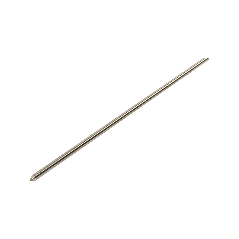
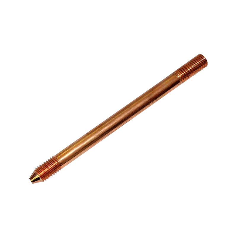
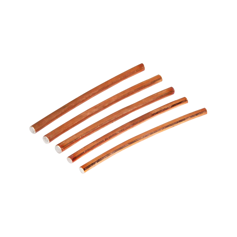
Section 250.52 lists permitted electrodes. Rod and pipe electrodes must be at least 8 feet long and installed below permanent moisture level. Copper-clad steel rods are common because they combine a steel core for strength with a copper outer layer for conductivity and corrosion resistance; stainless steel and chemical rods are used where soil conditions demand them.
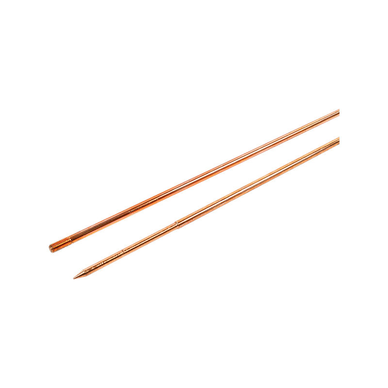 Copper Clad Steel Grounding Rod for Earthing SystemsA corrosion-resistant copper-clad steel grounding rod with long service life, low resistance, and connectors for deep, maintenance-free earthing installations.View Product →
Section 250.53 covers installation. If a single rod, pipe, or plate electrode has a resistance to earth above 25 ohms, Section 250.56 requires a supplemental electrode. Many installers simply drive a second rod because measuring 25 ohms is time-consuming. That is acceptable if the second rod is bonded properly. The 25-ohm rule is not a target; it is a trigger for a second electrode. You can read a practical explanation of the 25-ohm rule explained in the context of real installations.
Section 250.64 requires the grounding electrode conductor to be installed in one continuous length without splices, unless irreversible splices are used. It must be securely fastened and protected from physical damage where exposed. Section 250.66 sizes the grounding electrode conductor based on the largest service-entrance conductor. The table is not linear, and undersizing is a frequent plan-review comment.
| Service-entrance conductor (copper) | Minimum copper GEC | Minimum aluminum GEC |
|---|---|---|
| 2 AWG or smaller | 8 AWG | 6 AWG |
| 1/0 AWG through 3/0 AWG | 6 AWG | 4 AWG |
| 4/0 AWG through 350 kcmil | 4 AWG | 2 AWG |
| 400 kcmil through 600 kcmil | 2 AWG | 1/0 AWG |
| 650 kcmil through 900 kcmil | 1/0 AWG | 2/0 AWG |
| 1000 kcmil through 1200 kcmil | 2/0 AWG | 3/0 AWG |
Where Installations Go Wrong, and What Buyers Should Check
Most NEC 250 problems are not theoretical. They show up as red tags, rework, and delayed energization. Here are the failure points that matter most in the field.
1. Mixing connector materials without thinking about corrosion
Aluminum connectors on copper conductors create a galvanic couple. In damp or salty environments, that connection can degrade faster than the conductor itself. Listing and manufacturer instructions matter more than appearance. A clamp that fits mechanically may still be wrong for the conductor material and environment.
2. Assuming mechanical clamps stay tight forever
Mechanical clamps are acceptable, but they can loosen under thermal cycling, vibration, and soil movement. Buried connections are especially vulnerable because they are difficult to inspect. Exothermic welding creates a molecular bond between conductors. It is irreversible, does not loosen, and is often the preferred method for buried grounding electrode conductor splices and bonding jumpers. The trade-off is that it requires trained installers, proper molds, and correct weld powder for the conductor size and material.
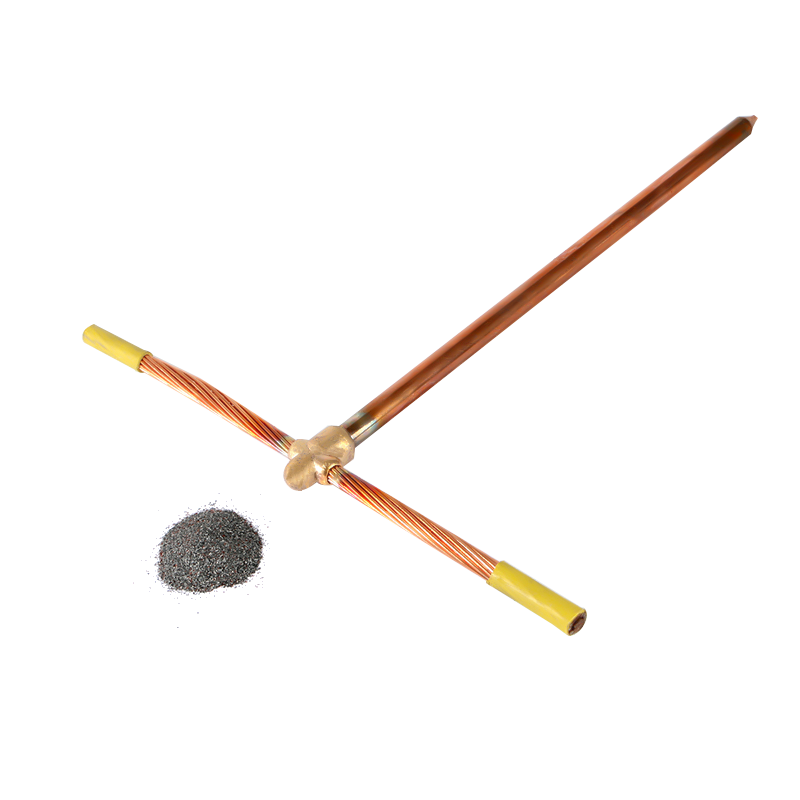 Exothermic Welding Powder for Grounding and Bonding ConnectionsSingle-use copper- or steel-based welding powder that creates durable, irreversible molecular bonds for grounding grids, lightning protection, and cable connections.View Product →
3. Undersizing the grounding electrode conductor
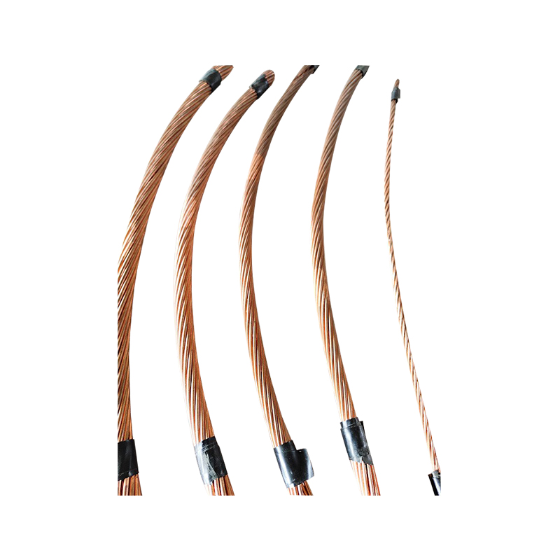
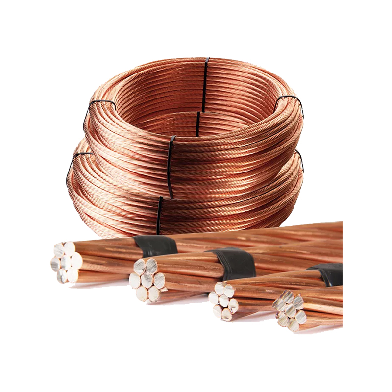
Table 250.66 is based on the largest service-entrance conductor, not on the load calculation. A 400 kcmil service does not use the same GEC as a 3/0 service. Using a smaller conductor because it fits a lug is a code violation. Copper-clad steel stranded wire is a common choice for GEC and bonding applications because it provides high tensile strength with a copper surface for conductivity. It also resists the nicking and bending damage that can affect solid conductors during installation.
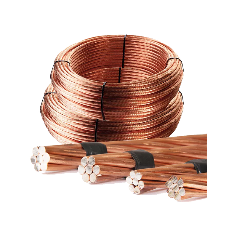 Copper Clad Steel Stranded Wire for Grounding and BondingFlexible copper-clad steel stranded conductor offering high tensile strength, corrosion resistance, and easier routing for grounding electrode and bonding applications.View Product →
4. Forgetting bonding of metal piping and structural steel
Section 250.104 requires metal water piping systems, and other metal piping systems that may become energized, to be bonded. If the building steel is a grounding electrode, it must be bonded to the grounding electrode system. These bonds are often missed because they are not part of the service equipment.
5. Leaving no way to test or inspect
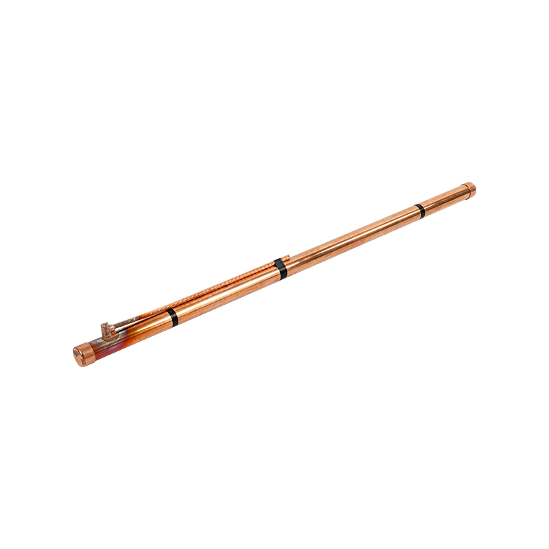
Ground rods and buried connections cannot be inspected after backfill. A grounding inspection pit or access well gives maintenance crews a safe way to measure resistance, verify connections, and add or replace components without excavation. That matters for facilities that must demonstrate ongoing compliance, such as substations, rail systems, and industrial plants.
A Practical NEC 250 Checklist
- Identify every available grounding electrode on the site, including concrete-encased electrodes, metal water piping, and building steel.
- Bond all electrodes into one grounding electrode system using listed irreversible connectors or exothermic welds.
- Size the grounding electrode conductor from Table 250.66 based on the largest service-entrance conductor.
- Add a supplemental electrode if a single rod, pipe, or plate electrode exceeds 25 ohms.
- Protect the GEC and all bonds from physical damage and corrosion, especially where they enter the earth.
- Install a grounding inspection pit or access point where testing and maintenance are required.
- Record resistance tests, material certificates, and weld inspections before backfill and energization.
NEC 250 compliance is not about buying the longest rod or the heaviest clamp. It is about treating grounding and bonding as a system: every electrode bonded, every conductor sized correctly, every connection made with a listed method, and every buried component protected and accessible for testing. The code gives you performance requirements and prescriptive tables, but the field decisions are yours. When you specify components, ask for material certificates, installation instructions, and test data. When you install, document the connection method and the resistance reading. That is how you avoid the red tag and keep the system reliable for the life of the facility.
 About Us
 +86-15167536268
 29, Xingmei Avenue, Xinchang, Zhejiang, China