

 English
 简体中文

A 400 A feeder is pulled through a crowded overhead rack above a mechanical room. The drawings call for 500 kcmil copper, the crew installs 500 kcmil copper, and the inspector still writes a correction notice. The conductor was never the problem. The ampacity was. NEC Article 310 is where that number is built, and it is the article most often read too quickly.
In short: Article 310 governs conductors for general wiring rated 2,000 volts and less. It sets minimum sizes, insulation and marking requirements, permitted uses, parallel conductor rules, and the ampacity tables and correction factors that decide the final figure on a panel schedule. It does not, by itself, size equipment grounding conductors, and it does not cover flexible cords or fixture wire. Knowing where that boundary sits saves more time than memorizing the tables.
What Article 310 Covers, and Where It Stops
The article applies to conductors installed in any of the Chapter 3 wiring methods, at 2,000 volts or less. Above that threshold, medium-voltage conductor requirements live in a separate article, and flexible cords, fixture wire and cable assemblies are handled elsewhere. Quoting Article 310 for a conductor it was never written to govern is the most common citation error on submittals.
Within its scope, the article answers five practical questions:
- How small may a conductor be? Fourteen AWG copper and 12 AWG aluminum or copper-clad aluminum are the floor for general wiring.
- What insulation and construction suits the environment of use?
- What must be printed on the jacket, and how legible must it stay?
- How many amps may it carry after ambient and bundling corrections?
- When may conductors be run in parallel?
One caution about citations. The article was reorganized after the 2017 cycle: ampacity moved into 310.14, the ampacity tables into 310.16 and 310.17, and the single-phase dwelling allowance into 310.12. A 2017 handbook and a 2023 handbook will point to different section numbers for the same rule. Cite the table and the edition, and confirm which cycle the authority having jurisdiction actually enforces.
Markings and Temperature Ratings Decide More Than You Think
Every conductor carries a jacket marking: size, insulation type, voltage rating, temperature rating, and manufacturer identification. The optional suffixes are where projects are won or lost. A -2 suffix means the insulation is rated 90 °C in both dry and wet locations. SUN RES indicates sunlight resistance, DIRECT BURIAL indicates suitability for direct burial, and OIL RES indicates oil resistance.
THHN pulled into an outdoor raceway is a recurring finding. THHN alone is a dry-location conductor; the wet-location versions are THWN and THWN-2, and only the -2 rating delivers 90 °C in wet conditions. If the jacket says THHN and the conduit drains condensate, the installation is non-compliant no matter how carefully the ampacity was calculated.
Temperature rating then works on two levels. The conductor has a rating and the termination has a rating, and the lower one governs. Most modern breakers and lugs are rated 75 °C, so a 90 °C conductor landed on a 75 °C lug is limited to its 75 °C ampacity. The 90 °C column remains useful for derating calculations, but the final result cannot exceed the termination limit.
6 AWG copper ampacity by temperature column (NEC Table 310.16)
Three Steps to a Defensible Ampacity Number
- Take the base ampacity from the applicable table for the conductor size, material and temperature rating.
- Apply the ambient temperature correction factor.
- Apply the adjustment factor for the number of current-carrying conductors in the raceway or cable.
Multiply, then compare against the termination limit and the overcurrent device. The smallest of those three values is the ampacity that survives inspection.
| Conductor (copper) | 60 °C | 75 °C | 90 °C |
|---|---|---|---|
| 14 AWG | 15 A | 20 A | 25 A |
| 12 AWG | 20 A | 25 A | 30 A |
| 10 AWG | 30 A | 35 A | 40 A |
| 8 AWG | 40 A | 50 A | 55 A |
| 6 AWG | 55 A | 65 A | 75 A |
| 4 AWG | 70 A | 85 A | 95 A |
| 2 AWG | 95 A | 115 A | 130 A |
| 1/0 AWG | 125 A | 150 A | 170 A |
| 4/0 AWG | 195 A | 230 A | 260 A |
| 250 kcmil | 215 A | 255 A | 290 A |
| 500 kcmil | 320 A | 380 A | 430 A |
Bundling is the factor most often missed. Neutrals count as current-carrying conductors in most multiwire branch circuits, and where harmonic loads are significant the code requires counting them. A raceway with six current-carrying conductors runs at 80 percent of table value before ambient correction even begins.
Adjustment factors by number of current-carrying conductors in a raceway or cable
Worked example: 1/0 AWG copper THWN-2 in a raceway, 75 °C column, 150 A base. The route crosses a mechanical room at 40 °C, giving a 0.88 correction, and the raceway holds six current-carrying conductors, giving 0.80. The result is 150 × 0.88 × 0.80 = 105.6 A. The next standard overcurrent device that does not exceed that value is 100 A. A schedule showing 125 A would be wrong twice over.
Parallel Conductors: Short Rules, Long Consequences
Parallel conductors are permitted only at 1/0 AWG and larger, and every set must match in length, material, circular mil area, insulation type and termination. Where sets run in separate raceways, those raceways must share the same physical characteristics. A crew that cuts one set two feet shorter than the rest has created an imbalance the code does not allow, even though nothing looks wrong from the ladder.
Grounding carries its own trap here. When parallel raceways are used, each raceway must contain a full-size equipment grounding conductor sized to the overcurrent device ahead of the circuit, not a fraction of it divided across the sets.
Where Article 310 Hands Off to the Grounding System
Article 310 tells you what a conductor is and what it may do. Article 250 tells you where grounding conductors go and how large they must be. Reading only one of the two is how grounding errors survive design review and surface during commissioning.
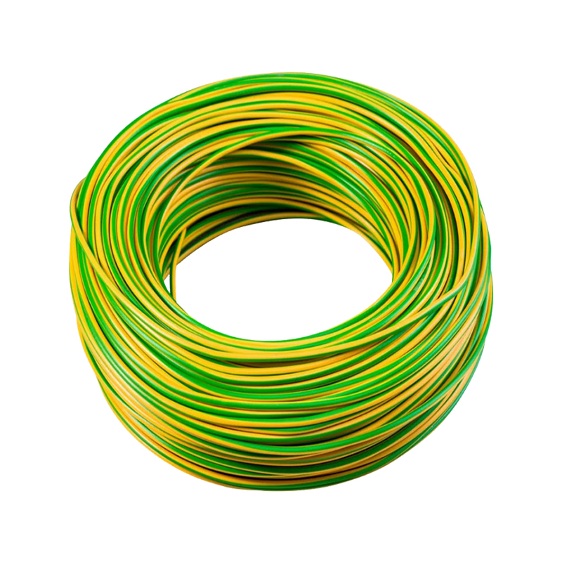
Equipment grounding conductors follow Table 250.122, sized by the rating of the overcurrent device ahead of the circuit rather than by the phase conductor. Identification matters as well: green, green with a yellow stripe, or bare. An insulated grounding conductor larger than 6 AWG may be re-identified at its terminations, but a phase conductor may never be re-identified as a grounding conductor.
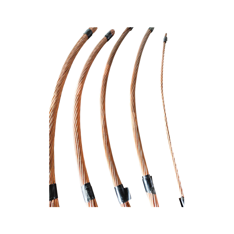
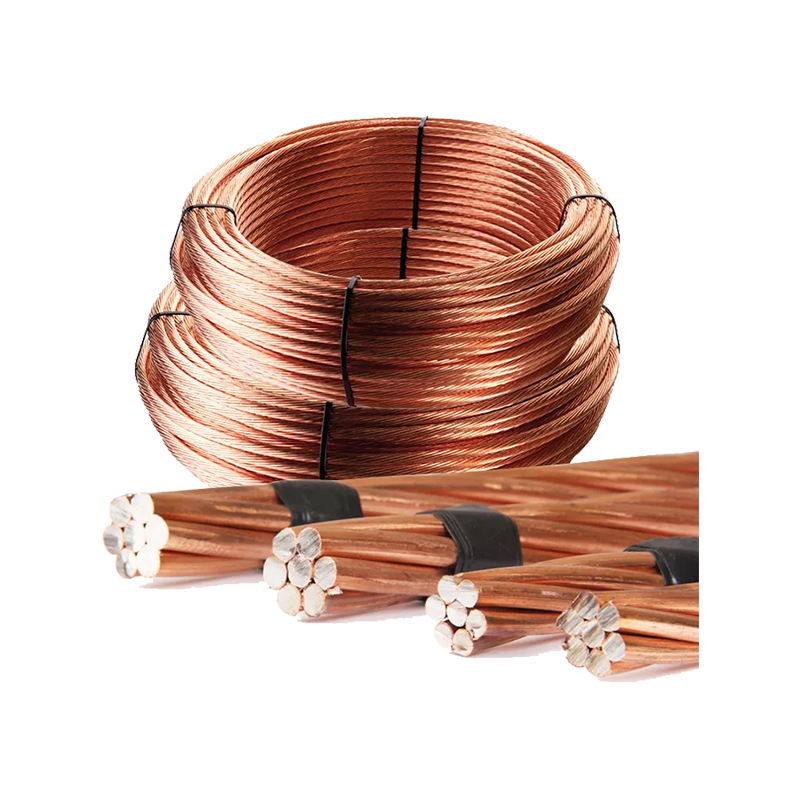
In the field, the conductor types used for grounding and bonding overlap heavily with general wiring: bare copper, green insulated copper, copper-clad steel and galvanized steel. The full range of earthing conductors used on substation and industrial work follows the same insulation and marking logic as any branch circuit conductor. A grounding conductor in a wet duct still needs moisture-resistant insulation, and a direct-burial run still needs a direct-burial rating.
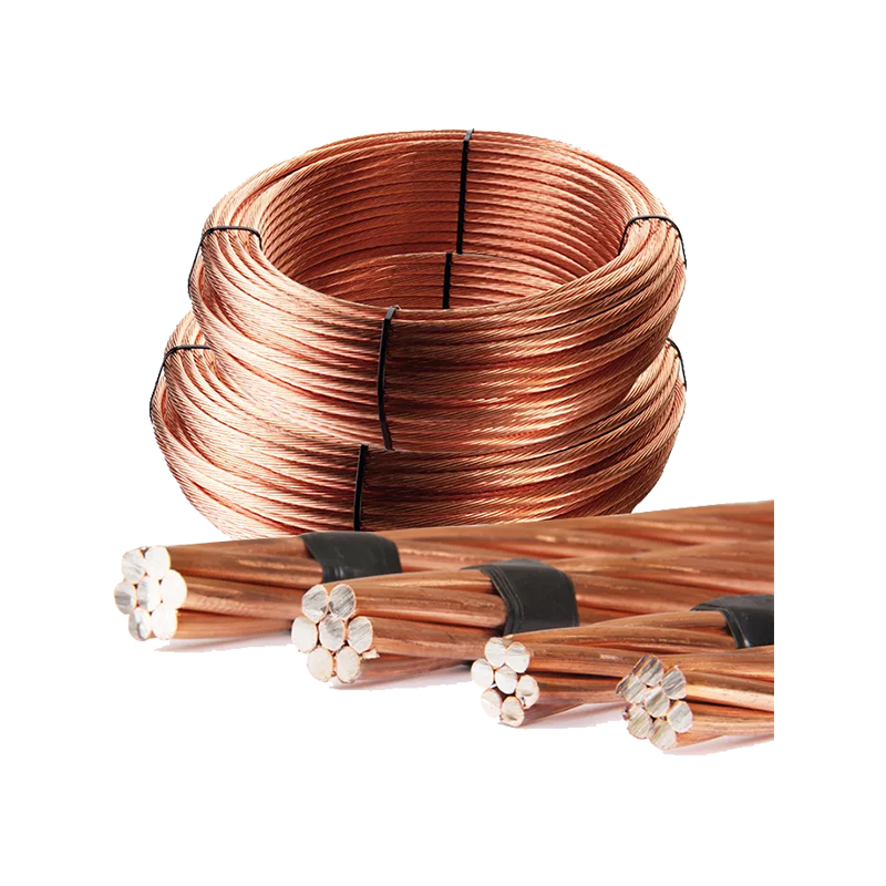 Copper-Clad Steel Stranded Wire for EarthingA flexible copper-clad steel grounding conductor that pairs copper conductivity with steel strength for demanding earthing installations.View Product →
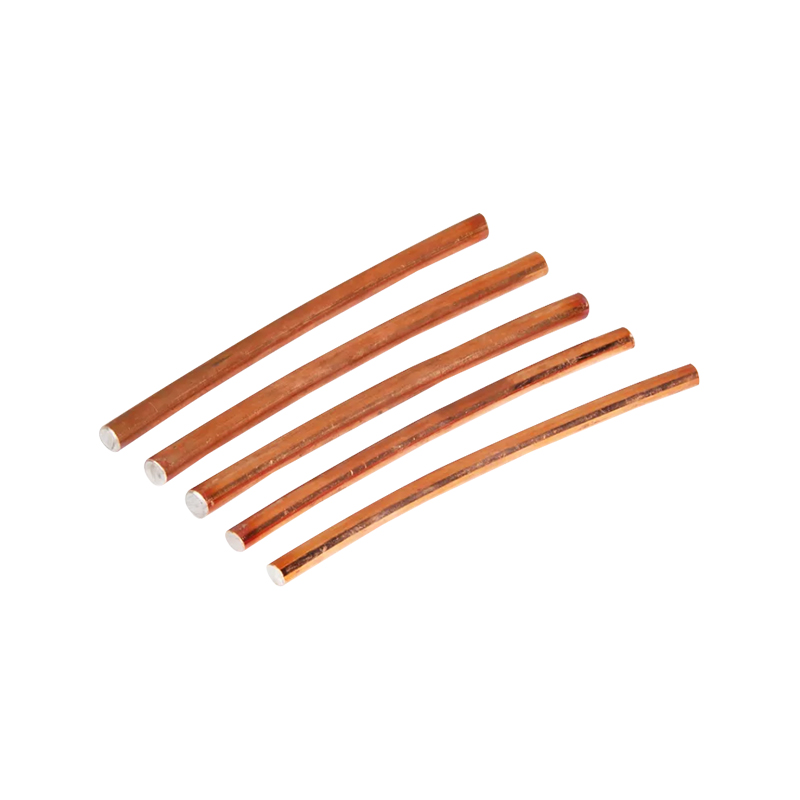
Material choice is the second decision. Copper conducts best and corrodes predictably, but it is a theft target on remote sites. Copper-clad steel trades a little conductivity for mechanical strength and a much lower scrap value. Galvanized steel is the cheapest and the shortest-lived in aggressive soil. The comparison between copper, copper-bonded steel and galvanized conductors usually comes down to soil chemistry and maintenance budget rather than to the code text.
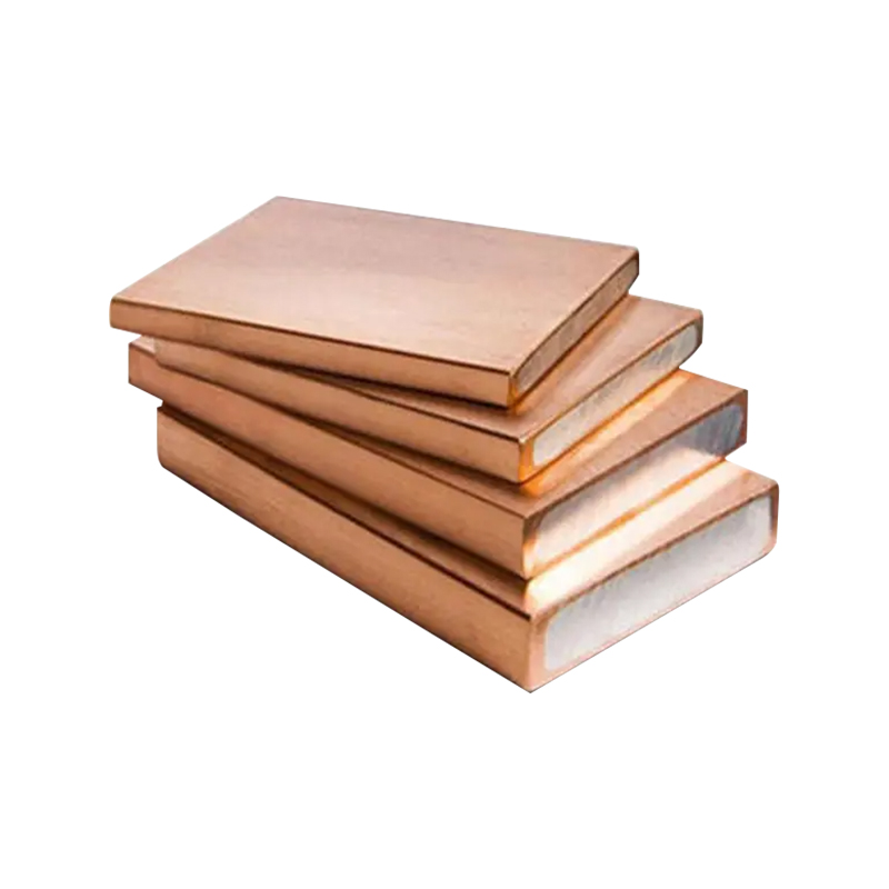
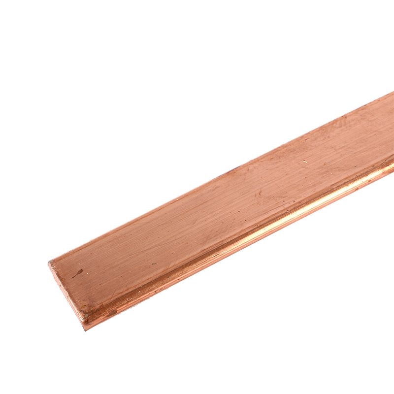 Oxygen-Free Copper Bar for Grounding and Lightning ProtectionA high-purity oxygen-free copper grounding bar for lightning protection and bonding, where conductivity and predictable corrosion matter.View Product →
Connections deserve equal attention. A conductor is only as good as its terminations, and the transition between copper and galvanized steel is exactly where galvanic corrosion begins. Exothermic welding removes the mechanical joint entirely and produces a connection that will not loosen under fault current or thermal cycling.
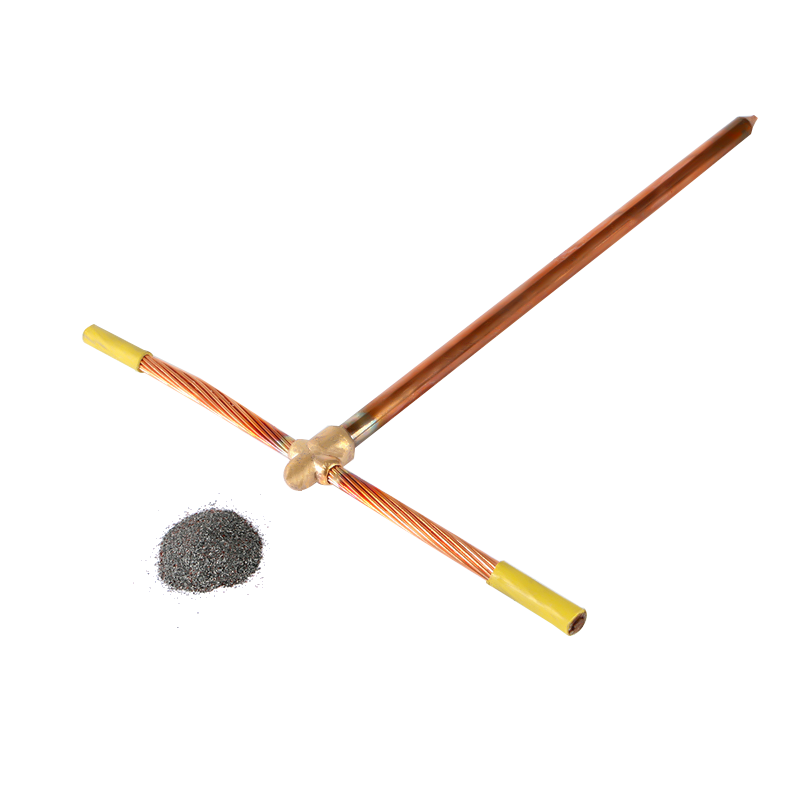 Exothermic Welding Powder for Grounding ConnectionsSingle-use welding powder that forms permanent grounding joints in graphite molds, avoiding mechanical terminations prone to loosening under fault current.View Product →
Findings That Repeat on Almost Every Project
- Ampacity read from the 90 °C column and applied directly against a 75 °C breaker.
- Neutral conductors left out of the bundling count.
- THHN specified where the route is wet, outdoors or underground.
- Parallel sets of unequal length, or mixed copper and aluminum sets.
- Equipment grounding conductors downsized across parallel raceways.
- Jacket markings painted over, taped, or worn away before inspection.
- Derating calculated at the panel but never carried through to the schedule.
Each of these is a documentation problem before it becomes an installation problem. A one-page ampacity worksheet attached to the submittal, showing table value, ambient factor, bundle factor, termination limit and final device size, closes most of them before the inspector arrives on site.
The Short Version
Article 310 is a calculation article wrapped around a materials article. Get the conductor type right for the environment, keep the jacket markings intact, and run the three-step ampacity math every time raceway fill or ambient temperature changes. Then check the termination rating before writing a number on a panel schedule. The conductors themselves are rarely the weak point in a wiring or grounding system; the assumptions behind their selection usually are.
 About Us
 +86-15167536268

 29, Xingmei Avenue, Xinchang, Zhejiang, China
